Electrolyteless fuel cell system

a fuel cell and electrolyte technology, applied in the direction of fuel cells, fuel cell details, electrical equipment, etc., can solve the problems of affecting the performance of fuel cells, and affecting the operation of fuel cells

Inactive Publication Date: 2017-12-07
SHAH EMANUEL E
View PDF0 Cites 0 Cited by
  • Summary
  • Abstract
  • Description
  • Claims
  • Application Information

AI Technical Summary

Benefits of technology

The patent describes a system and methods for an electrolyteless fuel cell. The system includes a negative or positive bias electrode and an electrical grid power supply that is either biased negative or positive with respect to the anode or cathode. The method involves oxidizing a fuel gas and reducing an oxidant on either the anode or cathode to create a positively or negatively charged molecule. The charged molecule is pulled through the electrical grid to the opposite pole where it generates an electric current. The system and methods allow for the efficient generation of electricity without the use of an electrolyte.

Problems solved by technology

If free electrons or other substances could pass through the electrolyte, they would disrupt the chemical reaction.
This voltage drop seriously affects the performance of a fuel cell.
Even with high cost platinum cathode the over potential is a serious problem that requires specific design considerations.
One of the parameters affecting the performance of a fuel cell cathode is temperature and with limitations on operating temperatures of many prior art fuel cells; the over potential problem is difficult to overcome.
For a cathode to have low over potential, it requires both good ion conductivity and electron conductivity which is difficult to achieve in prior art fuel cells.
However, individual fuel cells produce relatively small electrical potentials, typically only about 0.7 volts, with the energy efficiency being between about 40-60% due to heat loss.
One of the difficult problems faced by prior art high temperature fuel cells is the unequal thermal expansion of different components of the fuel cell.
This imposes limitations on the type of materials that can be used in the fuel cell and consequently, has a great effect on the cost, reliability and performance of the fuel cell.

Method used


Image

  • Electrolyteless fuel cell system
  • Electrolyteless fuel cell system
  • Electrolyteless fuel cell system

Examples


Embodiment Construction

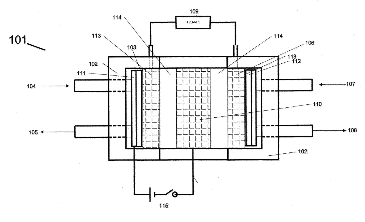
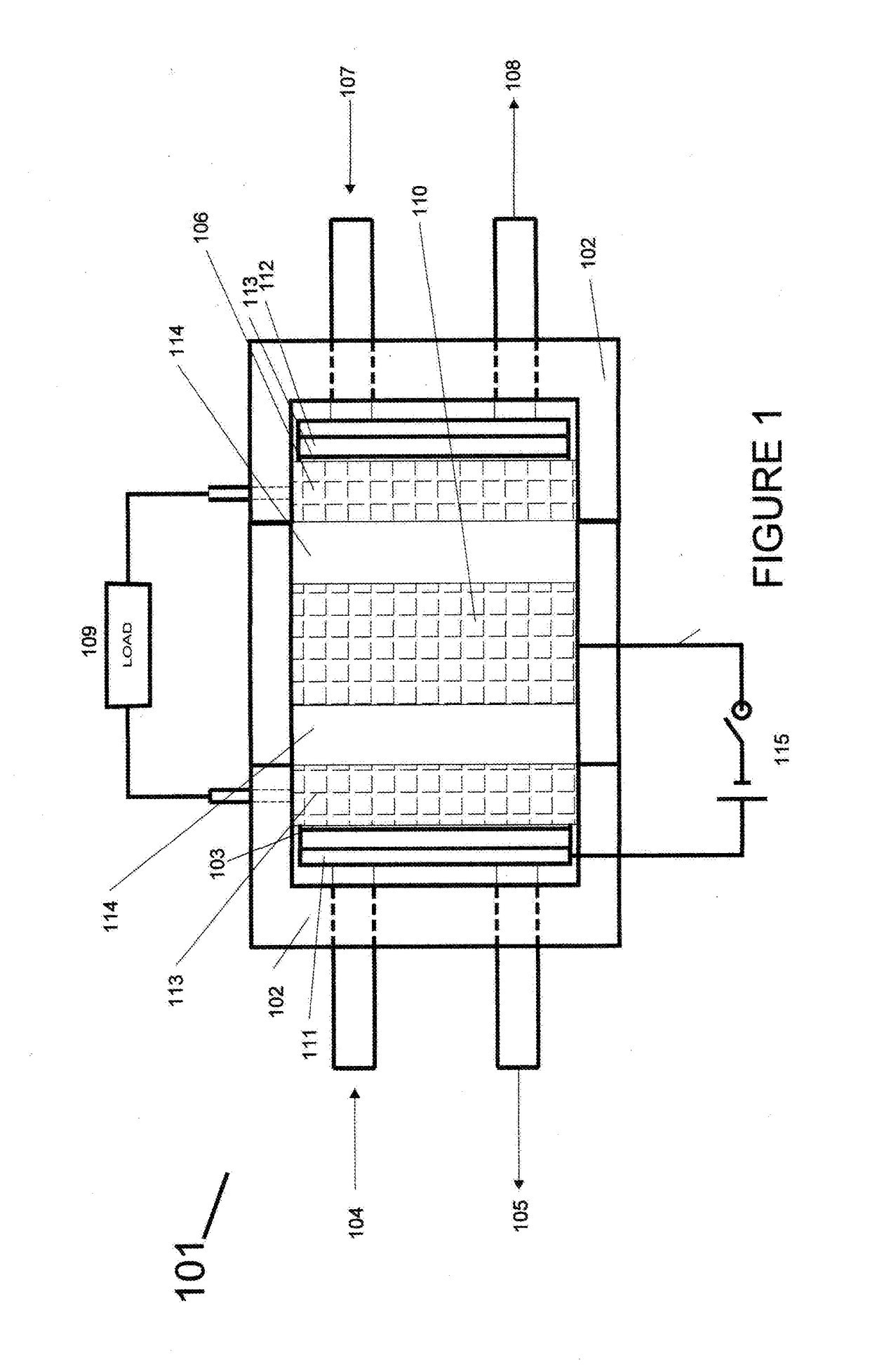
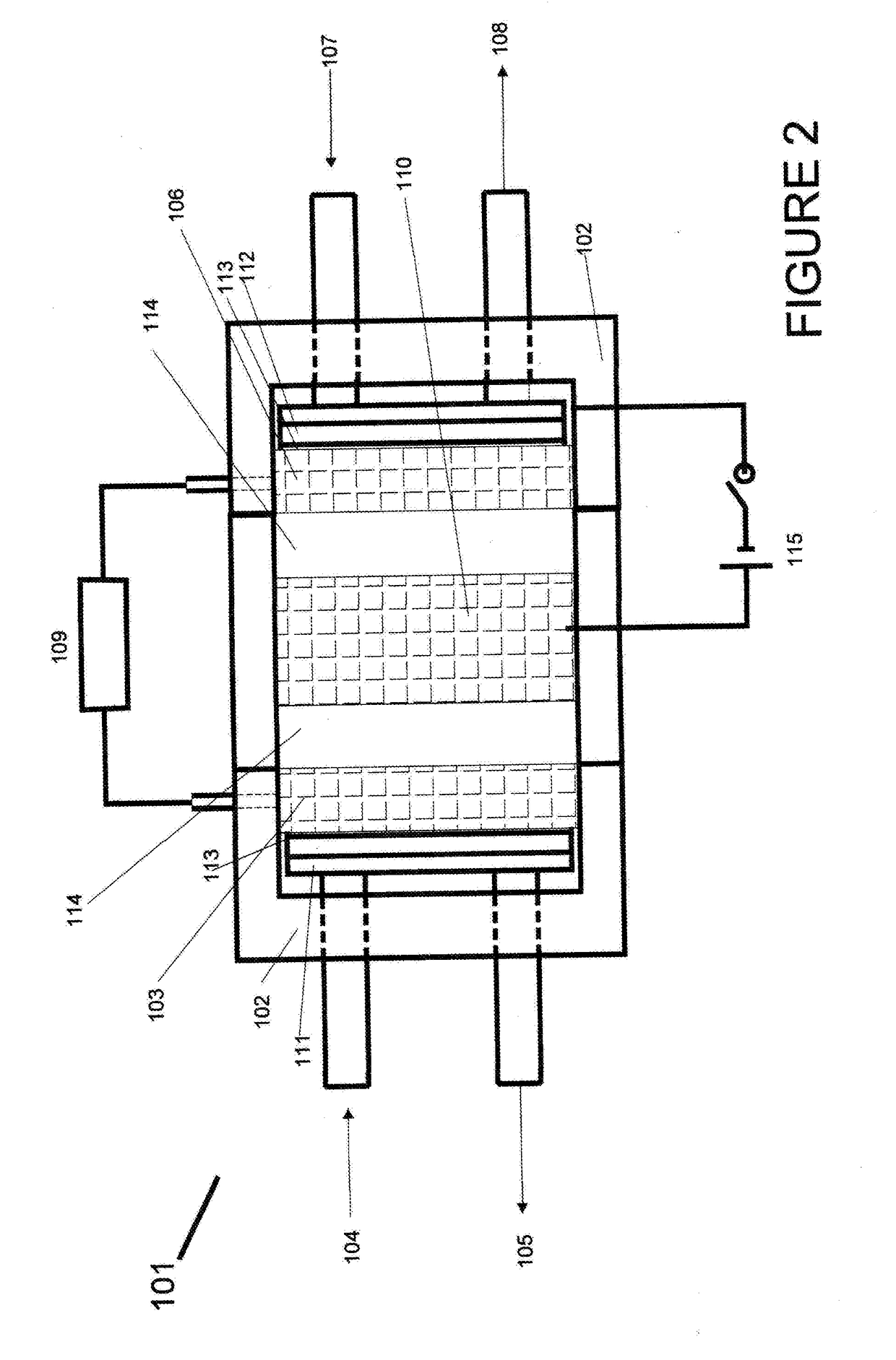
[0031]The disclosure provides an electrolyteless fuel cell system, which includes an anode; a cathode; an electrical grid between the anode and cathode; an anode side grid bias electrode; a cathode side grid bias electrode; and an electrical grid power supply, wherein the electrical grid is biased negative with respect to the anode through the anode side grid bias electrode and the electrical grid power supply, or wherein the electrical grid is biased positive with respect to the cathode through the cathode side grid bias electrode and the electrical grid power supply.

[0032]In one aspect, the disclosure provides an electrolyteless fuel cell system, wherein the electrical grid is biased negative with respect to the anode, to create a potential difference between the electrical grid and the anode, wherein incoming hydrogen is used as a fuel source at the anode.

[0033]In another aspect, the disclosure provides an electrolyteless fuel cell system, wherein the negatively biased electrical...


PUM


Abstract

An electrolyteless fuel cell system includes an anode; a cathode; an electrical grid between the anode and cathode; an anode side grid bias electrode; a cathode side grid bias electrode; and an electrical grid power supply, wherein the electrical grid is biased negative with respect to the anode through the anode side grid bias electrode and the electrical grid power supply, or wherein the electrical grid is biased positive with respect to the cathode through the cathode side grid bias electrode and the electrical grid power supply.

Description

TECHNICAL FIELD OF THE INVENTION[0001]The present invention generally relates to the field of fuel cell technology, and more particularly, to systems and methods for operating an electrolyteless fuel cell system.BACKGROUND OF THE INVENTION[0002]A fuel cell is an electrochemical cell that converts the chemical energy from a fuel into electricity through an electrochemical reaction of hydrogen containing fuel with oxygen or another oxidizing agent. Fuel cells are different from batteries in requiring a continuous source of fuel and oxygen (usually from air) to sustain the chemical reaction, whereas in a battery the chemical energy comes from chemicals already present in the battery. Fuel cells can produce electricity continuously for as long as fuel and oxygen are supplied.[0003]There are many types of fuel cells but they all consist of an anode, a cathode, and an electrolyte that allows positively or negatively charged ions to move between the two sides of the fuel cell. Fuel cells c...

Claims


Application Information

Patent Timeline
IPC IPC(8): H01M8/02H01M8/0258
CPCH01M8/0258H01M8/02H01M8/0247H01M8/04902Y02E60/50
Inventor SHAH, EMANUEL E.
Owner SHAH EMANUEL E
Why Eureka
Try Eureka