
Measuring of a physiological parameter using a wearable sensor

Active Publication Date: 2017-12-07
KONINKLJIJKE PHILIPS NV
View PDF15 Cites 11 Cited by
  • Summary
  • Abstract
  • Description
  • Claims
  • Application Information

AI Technical Summary

Benefits of technology

The patent text describes a device that uses an electroactive polymer actuator to monitor physiological parameters of a user wearing the device. The device can operate with low power consumption and can be small and light to minimize discomfort for the user. The actuator can adjust the position or configuration of the physiological parameter sensor by changing its contact pressure with the subject. This allows for accurate measurements even if the subject moves during the measurement process. The device can compensate for the movement of the physiological parameter sensor by adjusting the actuator to directly contact the sensor. This results in a force causing the sensor to move back to its original position, reducing the impact of movement on the measurement. The device can also use a second signal to accurate calculate the point at which the sensor begins to move and determine the magnitude of the actuation signal required to compensate for movement. Overall, the device provides a convenient and comfortable way to monitor physiological parameters of a person.

Problems solved by technology

An important problem with respect to wearable sensors is ensuring that the contact pressure or separation between the physiological parameter sensor and the user's body is maintained at a constant level since the signal obtained during physiological sensing is affected by the relative position of the wearable sensor and the user.
Therefore, one problem that can occur during monitoring of a physiological parameter using an apparatus including a wearable sensor is that the position of the sensor relative to the body of the user may change as a consequence of movement of the user, resulting in a change in the measured data.
Movement of the user resulting in a change in the relative position of the wearable sensor and the user causes motion artefacts to be present in the measured data.
While motion artefacts can be filtered out digitally, this approach can negatively impact the quality of the measurement data obtained using the wearable sensor.

Method used


Image

  • Measuring of a physiological parameter using a wearable sensor
  • Measuring of a physiological parameter using a wearable sensor
  • Measuring of a physiological parameter using a wearable sensor

Examples


Embodiment Construction

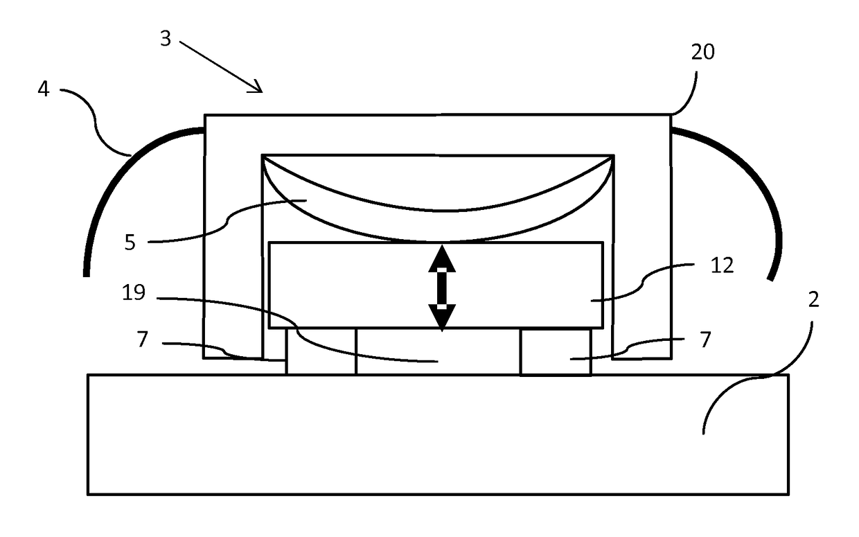
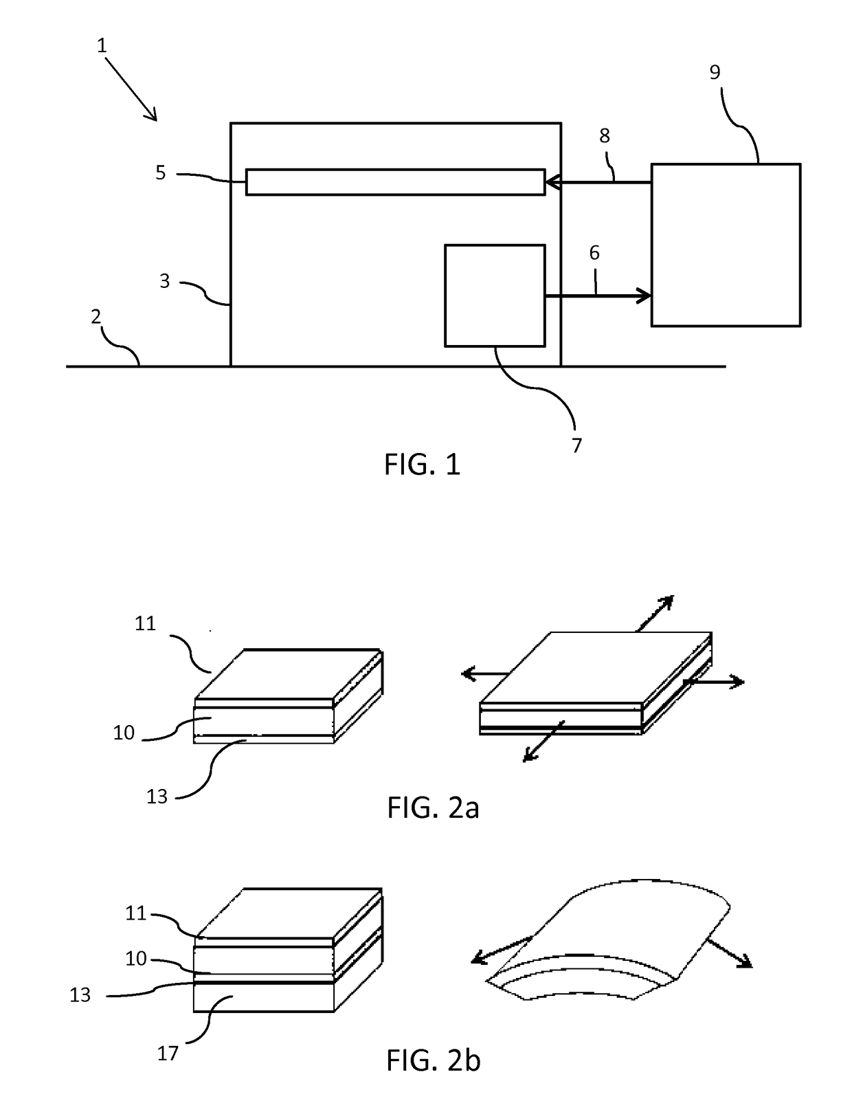
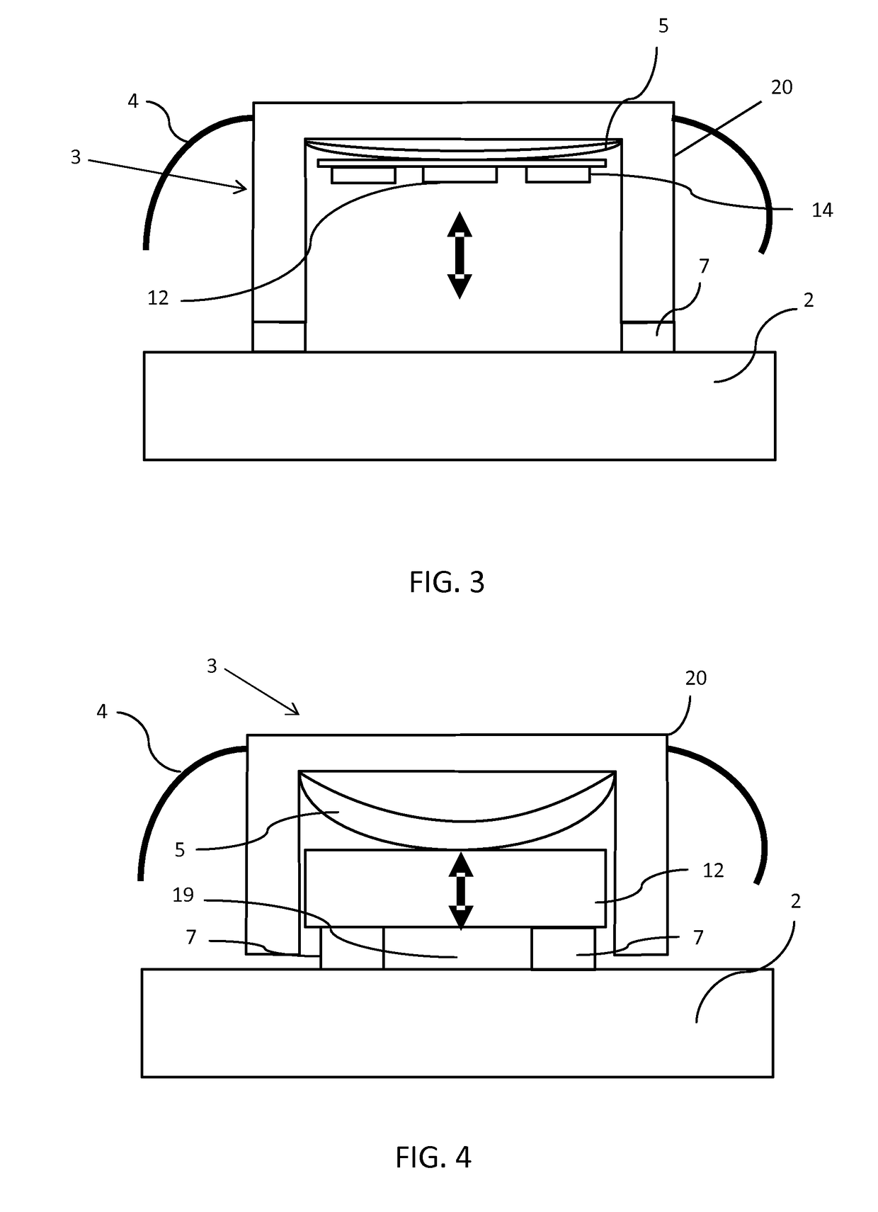
[0061]FIG. 1 is a schematic block diagram illustrating an apparatus 1 according to an example of the invention. The invention provides an apparatus 1 including a physiological parameter sensor 3 adapted to be worn by a subject; an actuator 5, comprising an electroactive polymer material, for adjusting the position of the physiological parameter sensor 3 relative to the subject 2; a feedback sensor 7 for measuring movement of the physiological parameter sensor relative to the subject and a controller 9 configured to process measurements of the feedback sensor 7 and to adjust the position of the actuator 5 based on information from the feedback sensor 7.

[0062]The feedback sensor 7 is arranged to detect relative movement of the physiological parameter sensor 3 with respect to the user's body 2. For example, the feedback sensor 7 may be a contact sensor arranged to detect if the physiological parameter unit is in contact with the subject. For example, the feedback sensor may be an optic...


PUM


Abstract

An apparatus comprises a sensor for measuring a physiological parameter of a subject, wherein the physiological parameter sensor is adapted to be worn by the subject; an actuator comprising an electro-active polymer material, EAP, portion for adjusting the position of the physiological parameter sensor relative to the subject; a feedback sensor for measuring movement of the physiological parameter sensor and / or the subject; a controller configured to process the measurements of the feedback sensor and to adjust the position of the actuator based on information from the feedback sensor.

Description

FIELD OF THE INVENTION[0001]This invention relates to sensors for measuring a physiological parameter of a subject, wherein the sensor can be worn by a user. For example a wearable photoplethysmographic (PPG) sensor, a wearable electrocardiogram sensor, a wearable ultrasound sensor, a wearable heart rate sensor, or a wearable skin monitoring sensor. In particular, the invention relates to an apparatus comprising a wearable sensor for maintaining contact or maintaining a particular distance of separation between the wearable sensor and the user.BACKGROUND OF THE INVENTION[0002]It is becoming increasingly popular to monitor a physiological parameter of a subject using an apparatus including a wearable device. Such devices are convenient to use as they offer increased freedom of movement for the user whilst a physiological parameter is being monitored. In this way, it is possible to measure physiological parameters in a variety of circumstances, for example at different levels of physi...

Claims


Application Information

Patent Timeline
IPC IPC(8): A61B5/00A61B8/00A61B5/024A61B5/0402H01L41/193H01L41/09A61B5/332
CPCA61B5/6843A61B5/02427A61B5/0402H01L41/193A61B5/02438H01L41/09A61B8/44A61B5/6824A61B5/6844A61B5/7207A61B5/02416A61B5/14551A61B5/25F03G7/005A61B5/318H10N30/20H10N30/857
Inventor VAN DEN ENDE, DAAN ANTONHAAKMA, REINDERJOHNSON, MARK THOMASBOEKHORST, FREDERICK MARIAKOVACEVIC MILIVOJEVIC, MILICAHAKKENS, FRANCISCUS JOHANNES GERARDUSHILGERS, ACHIMHENDRIKS, CORNELIS PETRUSUBACHS, RENE LEONARDUS JACOBUS MARIEPELSSERS, EDUARD GERARD MARIE
Owner KONINKLJIJKE PHILIPS NV
Learn More