
Refrigerant vent rectifier and efficiency booster

a technology of refrigerant vent and rectifier, which is applied in the direction of refrigeration components, liquefaction, lighting and heating apparatus, etc., can solve the problems of limiting the production capacity of the plant, petrochemicals that are high energy consumption, and vaporization and heating can be energy-use-intensiv

Active Publication Date: 2017-11-30
LINDE AG
View PDF4 Cites 0 Cited by
  • Summary
  • Abstract
  • Description
  • Claims
  • Application Information

AI Technical Summary

Benefits of technology

The refrigeration system described in this patent allows for the recovery and reuse of refrigeration. This can help alleviate problems related to limited refrigeration capacity, reducing the need for additional equipment or modifications to the plant. Recovered refrigeration can also be used to lower energy consumption and operating costs.

Problems solved by technology

For example, the recovery of olefins from gas mixtures is an economically important but highly energy intensive petrochemical process.
Nitrogen vaporizes below −14° C. The vaporizing and heating can be energy use intensive.
Inherent limitations of the refrigeration system often limit the production capacity of the plant, which in the industry is referred to as a “bottleneck”.
To relieve this bottleneck, the addition of refrigeration capacity may be necessary, in which case, expensive modifications or replacement of compressors, heat exchangers, drums and the like may be required.

Method used


Image

  • Refrigerant vent rectifier and efficiency booster
  • Refrigerant vent rectifier and efficiency booster
  • Refrigerant vent rectifier and efficiency booster

Examples


first embodiment

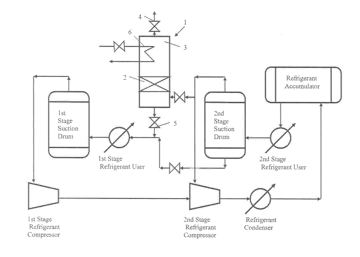
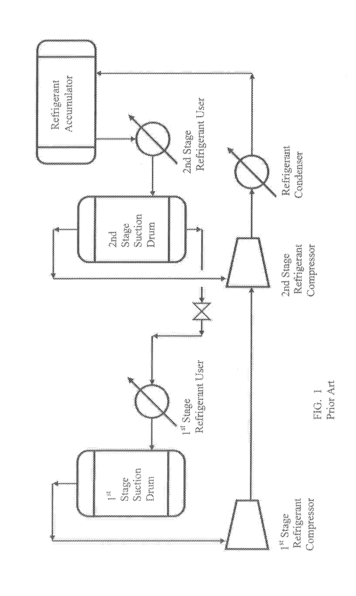
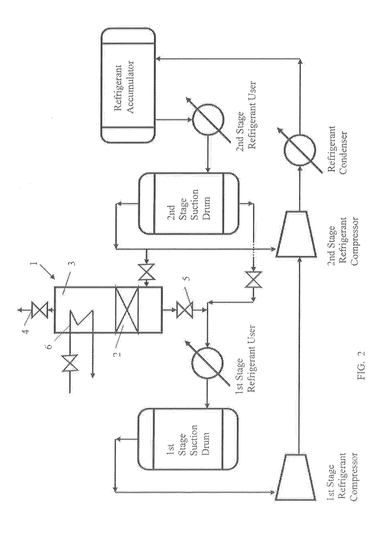
[0017]the invention nail be described with reference to FIG. 2. FIG. 2, includes all of the components described in FIG. 1 above for a refrigeration system. In particular, the refrigeration system of the invention includes 1st and 2nd Stage Refrigerant Compressors, 1st and 2nd Stage Suction Drums, a Refrigerant Condenser, and a Refrigerant Accumulator, that operate as described above to provide refrigerant to 1st and 2nd Stage Refrigerant Users.

[0018]For purposes of explaining the operation of the refrigeration system of the invention, the discussion that follows, refers to use in an ethylene production plant. The refrigeration system according to the invention includes a Refrigerant Vent Rectifier 1, as shown in FIG. 2. The rectifier 1 has a generally cylindrical cross section and is used to process some of the vapor from the 2nd Stage Suction Drum which is diverted to the rectifier 1. The diverted vapor is fed into a lower section of the rectifier 1, and passes up through a packed...

second embodiment

[0019]As shown in FIG. 2, nitrogen used in the rectifier exits from the heat exchanger 6. This nitrogen is not warm enough for use in the plant and so would need to be warmed before use. Therefore according to the invention as shown in FIG. 3, the nitrogen is further processed to raise the temperature thereof. The nitrogen leaving the heat exchanger 6, is heated against the refrigeration process in order to save additional power. A portion of the vapor from the 2nd Stage Refrigerant Compressor is desuperheated and condensed against the nitrogen from the heal exchanger 6, in a Nitrogen Heater. The refrigerant from the 2nd Stage Refrigerant Compressor is hot enough to warm the nitrogen sufficiently so that nitrogen leaving the nitrogen heater can be used elsewhere in the plant. The refrigerant exiting the Nitrogen Heater is returned to the process between the 2nd Stage Suction Drum and the 1st Stage Refrigerant User.

[0020]In some cases, the refrigerant does not require removal of iner...


PUM


Abstract

A refrigeration system for use in petrochemical plants, such as an ethylene production plant includes a refrigerant vent rectifier. The rectifier purifies the refrigerant by removing low molecular weight inerts. The refrigeration system is more efficient, consumes less energy and increases plant capacity.

Description

BACKGROUND OF THE INVENTION[0001]The invention relates to the use of liquid nitrogen to enhance the operation of a closed loop refrigeration system for industrial plants.[0002]Many industrial processes require refrigeration systems. For example, the recovery of olefins from gas mixtures is an economically important but highly energy intensive petrochemical process. In general, the gas mixtures are produced by hydrocarbon pyrolysis in the presence of steam (via thermal cracking, fluid catalytic cracking or fluid coking processes). Thereafter, Cryogenic separation methods are commonly used to recover the olefins, such methods requiring large amounts of refrigeration at low temperatures.[0003]A more specific example is an ethylene production plant. Refrigeration is required to separate desired products from the cracking heater effluent. The refrigeration may be provided by water cooling, closed cycle propylene and ethylene systems, or work expansion of pressurized light gases from the ...

Claims


Application Information

Patent Timeline
IPC IPC(8): F25J3/08F25J3/02
CPCF25J3/08F25J2270/42F25J2215/62F25J3/0238F25B1/10F25B5/04F25B9/002F25B43/043F25B2400/13F25B2400/23F25J1/0052F25J1/0085F25J1/025F25J1/0268F25J1/0274F25J3/0219F25J3/0252F25J2210/12F25J2210/42F25J2270/12F25J2270/60F25J2270/902F25J2270/904F25J2290/80
Inventor WHITNEY, MARKULRICH, MARK
Owner LINDE AG
Learn More