Sliding Vane Type Compressor and Exhaust Structure Thereof

a compressor and sliding vane technology, applied in the field an exhaust structure thereof, can solve the problems of wasting power consumption unable to discharge remaining gas from bump bodies of sliding vane compressors, and low energy efficiency, so as to reduce the exhaust loss of the compressor and reduce the production cost

Active Publication Date: 2017-11-30
ZHUHAI GREE REFRIGERATION TECH CENT OF ENERGY SAVING & ENVIRONMENTAL PROTECTION
View PDF2 Cites 5 Cited by
  • Summary
  • Abstract
  • Description
  • Claims
  • Application Information

AI Technical Summary

Benefits of technology

[0003]A main objective of the present application is to provide a sliding vane type compressor and an exhaust structure thereof, which could reduce production cost of sliding vane type compressors and reduce exhaust loss thereof.
[0014]By applying the technical solutions of the present application, during working, the compressed refrigerant could enter into the vent hole directly from the compression cavity and then be exhausted. The remaining refrigerant can also enter into the guiding passage through the exhaust passage and be then exhausted. Compared with the prior art structure of providing a side exhaust port and an exhaust valve disc at a side of the air cylinder, the vent hole of the exhaust structure of the present sliding valve type compressor can be set without being limited by the structure of the air cylinder, resulting in a large effective exhaust area. Besides, when the sliding vane type compressor exhausts gas, the sliding value type compressor needn't overcome the rigidity of the exhaust valve disc per se, such that the exhaust pressure is equal to back pressure, effectively reducing power consumption and manufacturing costs of the sliding vane compressor.

Problems solved by technology

At the same time, due to structural constraints, the sliding vane compressor side exhaust has a smaller effective area but a larger exhaust resistance and loss, consequently a lower energy efficiency.
In addition, due to a large clearance volume existing in the exhaust port 2, the remaining gas cannot be discharged from a bump body of the sliding vane type compressor.
As the sliding vane continues to rotate, the remaining high pressure gas expands to a lower pressure chamber therebehind, which needs to repeat the compression, thereby wasting power consumption of the sliding vane type compressor.

Method used


Image

  • Sliding Vane Type Compressor and Exhaust Structure Thereof
  • Sliding Vane Type Compressor and Exhaust Structure Thereof
  • Sliding Vane Type Compressor and Exhaust Structure Thereof

Examples


Embodiment Construction

[0023]It is to be noted that the features in the embodiments and examples in the present application may be combined with each other without conflict. Hereinafter, the present application will be described in detail with reference to the accompanying drawings.

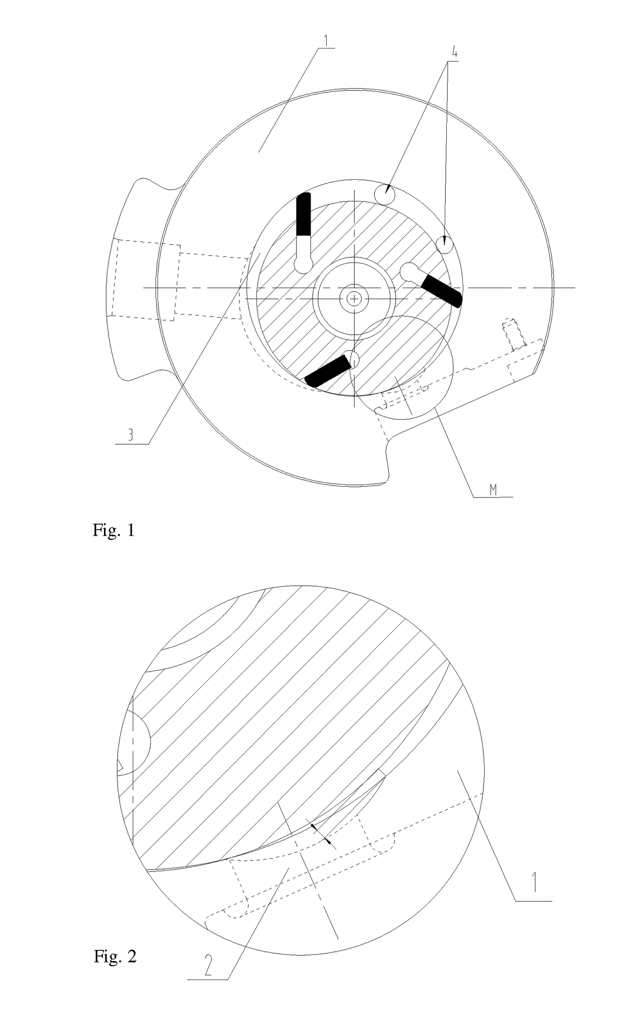
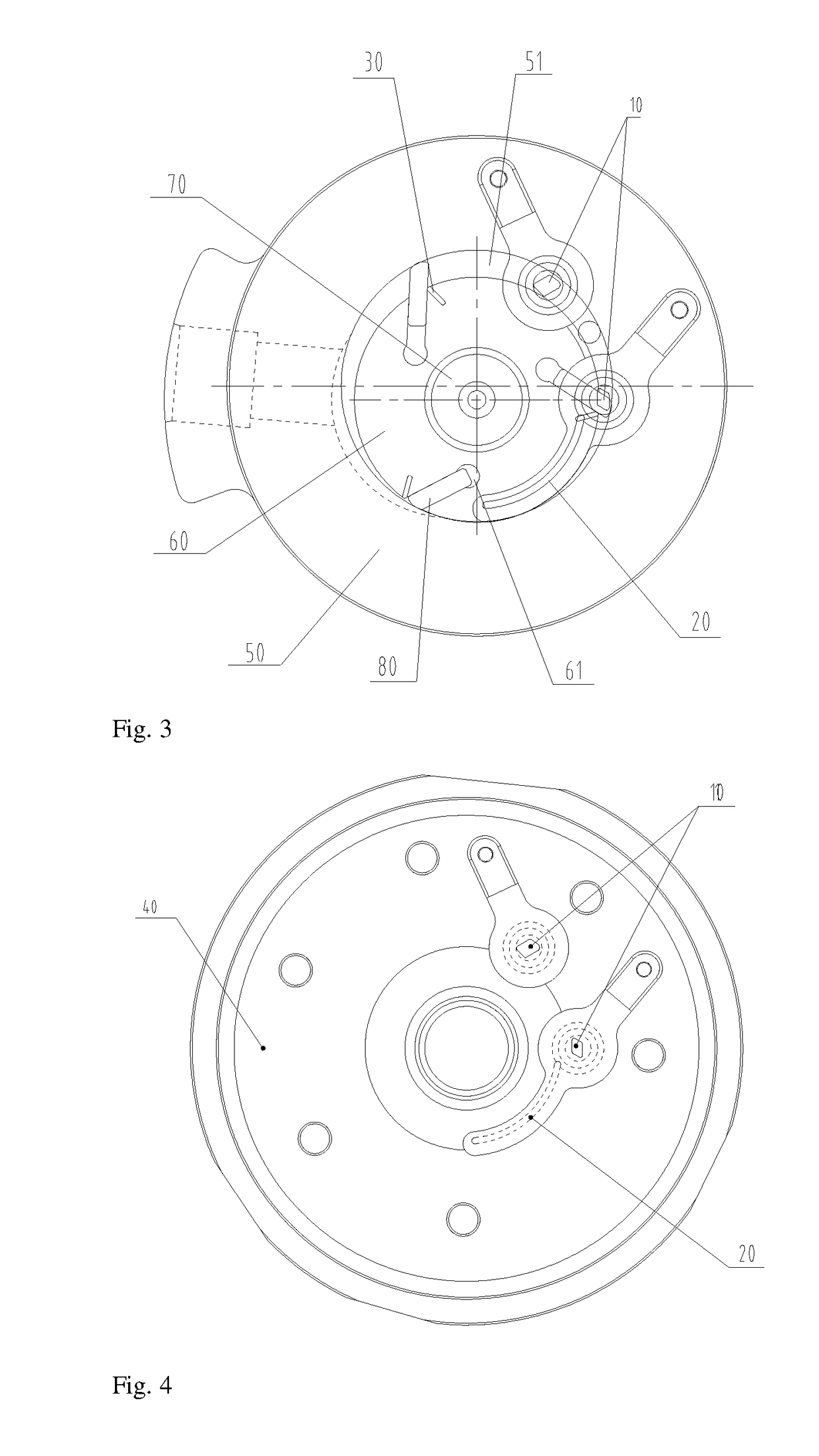
[0024]Referring to FIGS. 3 to 5, according to an embodiment of the present application, there is provided a sliding vane type compressor. The sliding vane type compressor includes a housing (not shown), a pump body (not shown), an air cylinder 50, and an upper flange 40 and a lower flange (not shown). The housing encloses a mounting cavity for mounting the pump body, the air cylinder, and the upper and lower flanges. The pump body includes a rotary shaft 70 and an eccentric circle 60 provided on the rotary shaft 70. A sliding vane groove 61 for mounting the sliding vane 80 is provided on the eccentric circle 60.

[0025]During mounting, the rotary shaft 70 is mounted on and passes through the air cylinder 50; the eccentric circle ...


PUM


Abstract

Disclosed are a sliding vane compressor and an exhaust structure thereof. The exhaust structure of the sliding vane compressor includes: an exhaust hole, the exhaust hole being formed in a flange of the sliding vane compressor and being in communication with a compression cavity of a cylinder of the sliding vane compressor; a guide channel, the guide channel being formed on the flange and penetrating through the flange; and an exhaust channel, the exhaust channel being formed on an eccentric circle of the sliding vane compressor, and the exhaust channel being used for communicating the compression cavity with the guide channel using the rotation of the eccentric circle. The sliding vane compressor and the exhaust structure thereof have a small exhaust loss, thereby effectively reducing the power consumption and the production and manufacturing costs of the sliding vane compressor.

Description

FIELD OF THE INVENTION[0001]The present application relates to the field of air conditioners, and more particularly, to a sliding vane type compressor and an exhaust structure thereof.BACKGROUND OF THE INVENTION[0002]Referring to FIGS. 1 and 2, most of current sliding vane type compressors are provided with a cylinder 1 side exhaust structure. In order to ensure the normal use of various working conditions, besides usually providing an exhaust port 2 and an exhaust valve disc at a compression ending position, an intermediate exhaust port 4 is also provided at a middle position of a compression cavity 3. Further, an exhaust valve disc (also referred to as a pressure relief valve) is also provided to prevent overpressure in a low load working condition. At the same time, due to structural constraints, the sliding vane compressor side exhaust has a smaller effective area but a larger exhaust resistance and loss, consequently a lower energy efficiency. In addition, due to a large cleara...

Claims


Application Information

Patent Timeline
Patent Type & Authority Applications(United States)
IPC IPC(8): F04C18/344F04C29/12
CPCF04C29/12F04C18/3441F04C15/0049F04C2240/20F01C21/0809F04C29/06F04C18/344
Inventor WAN, PENGKAIXU, JIAREN, LIPINGLUO, FAYOUWU, FEI
Owner ZHUHAI GREE REFRIGERATION TECH CENT OF ENERGY SAVING & ENVIRONMENTAL PROTECTION
Why Eureka
Try Eureka