
Projector and light source module

Active Publication Date: 2017-11-23
CORETRONIC
View PDF10 Cites 0 Cited by
  • Summary
  • Abstract
  • Description
  • Claims
  • Application Information

AI Technical Summary

Benefits of technology

The invention provides a projector with a light source module that has a qualified cooling effect in various using states, which results in a longer usage life for the light source. The light source module includes a first airflow control assembly that controls the cooling airflow through an angle greater than 0 degrees and less than 90 degrees, ensuring the cooling airflow is directed to the light source in different states. This allows for improved cooling regardless of the projector's usage pattern, resulting in a longer lifespan for the light source.

Problems solved by technology

Because of the projector has different cooling conditions in response to the horizontal installation, vertical installation or portrait installation, an improper installation may lead to a poor cooling effect if there is a need to switch the projection angle; and consequently, the usage life of the lamp may be significantly reduced.

Method used


Image

  • Projector and light source module
  • Projector and light source module
  • Projector and light source module

Examples


Embodiment Construction

[0027]In the following detailed description of the preferred embodiments, reference is made to the accompanying drawings which form a part hereof, and in which is shown by way of illustration specific embodiments in which the invention may be practiced. In this regard, directional terminology, such as “top”, “bottom”, “front”, “back”, etc., is used with reference to the orientation of the Figure(s) being described. The components of the invention can be positioned in a number of different orientations. As such, the directional terminology is used for purposes of illustration and is in no way limiting. On the other hand, the drawings are only schematic and the sizes of components may be exaggerated for clarity. It is to be understood that other embodiments may be utilized and structural changes may be made without departing from the scope of the invention. Also, it is to be understood that the phraseology and terminology used herein are for the purpose of description and should not b...


PUM


Abstract

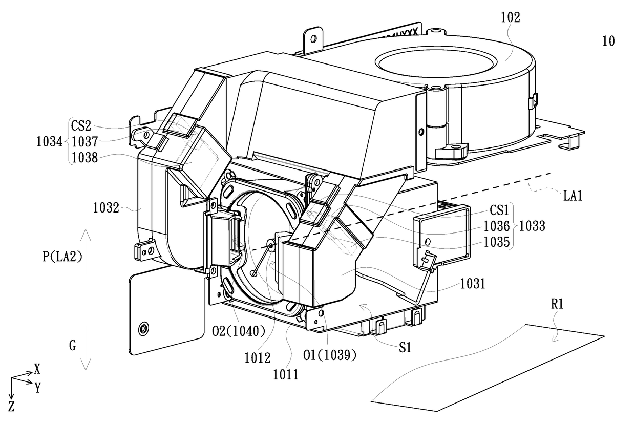
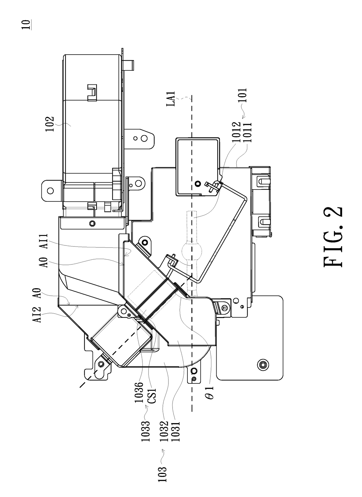
A light source module of a projector includes a light source having a lamp axis, a fan for providing a cooling airflow, and a flow guide device disposed between the light source and the fan and for guiding the cooling airflow. The flow guide device includes a first air channel connected between a side of the light source and an air outlet of the fan, a second air channel connected between another side of the light source and the air outlet of the fan, and a first airflow control assembly disposed in the first air channel and for controlling the first air channel either in communication or non-communication states via gravity. The first airflow control assembly has a first control rotating shaft inclined relative to the lamp axis and a first included angle between the first control rotating shaft and the lamp axis is less than 90 degrees.

Description

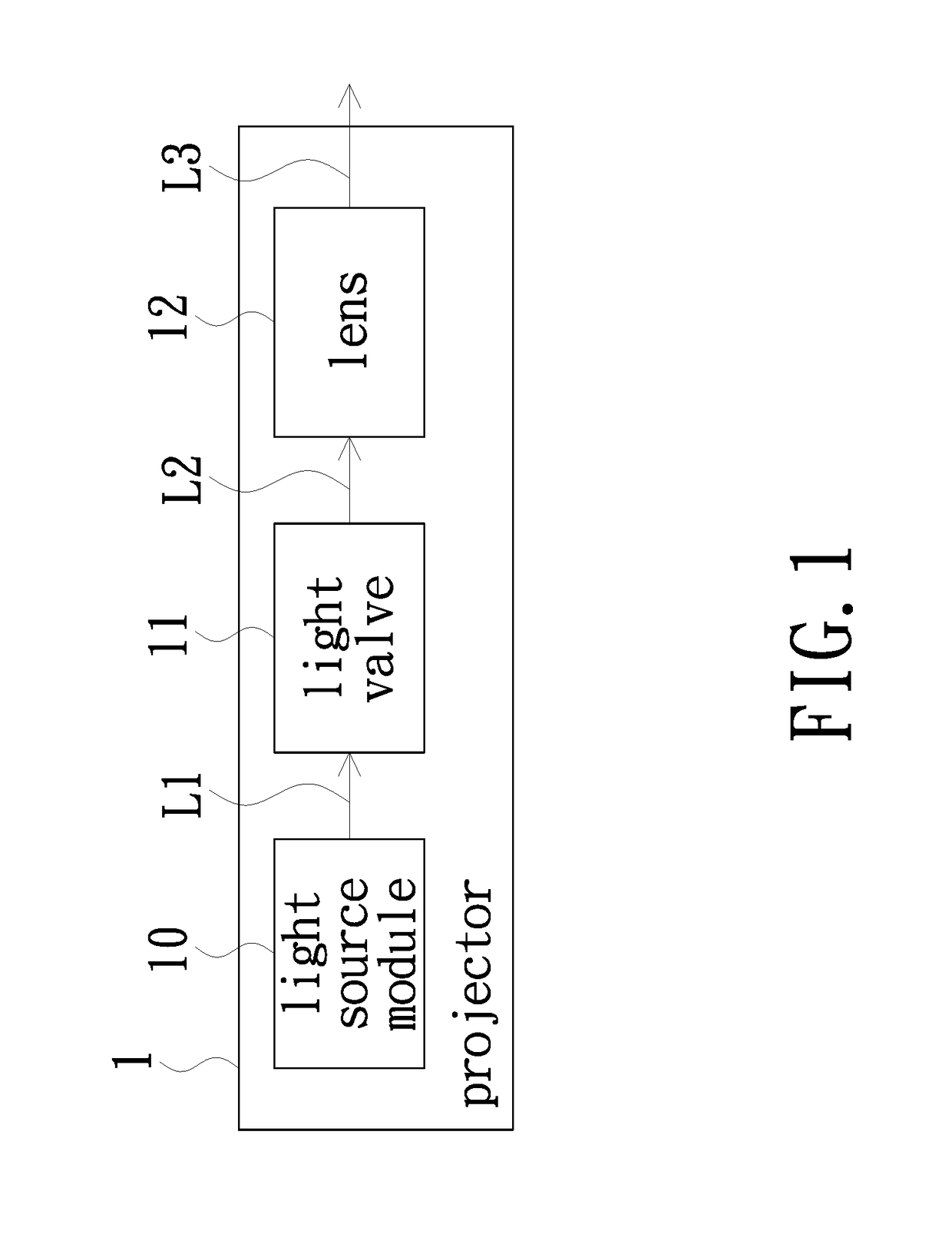
CROSS-REFERENCE TO RELATED APPLICATION[0001]THIS application CLAIMS THE PRIORITY BENEFIT OF CHINA APPLICATION OF CN201610328044.6 FILED ON 2016 May 17. THE ENTIRETY OF THE ABOVE-MENTIONED patent application IS HEREBY INCORPORATED BY REFERENCE HEREIN AND MADE A PART OF THIS SPECIFICATION.FIELD OF THE INVENTION[0002]The invention relates to a projector, and more particularly to a projector having a light source module.BACKGROUND OF THE INVENTION[0003]With the development of technology, the application of projector becomes more and more diverse and the installation of projector is not limited to horizontal installation (i.e., table top or ceiling mount). A projector needs a vertical installation when upward projection or downward projection is required; or, a projector needs a portrait installation (or portrait mode) if beam-up or beam-down is required. For a projector using a high pressure mercury lamp as a light source, in order to maintain a certain lamp life, the projector has diff...

Claims


Application Information

Patent Timeline
IPC IPC(8): G03B21/16G03B21/00F21V29/61G03B21/20F21V29/503
CPCG03B21/16G03B21/005F21V29/61F21V29/503G03B21/2093G03B21/20H04N9/3144
Inventor CHU, WEN-HAOCHEN, TE-TANGLIN, TSUNG-CHING
Owner CORETRONIC
Learn More