
Ultra-compact mass analysis device and ultra-compact particle acceleration device

a mass analysis and ultra-compact technology, applied in the direction of instruments, tube electrostatic deflection, particle separator tube details, etc., can solve the problems of large size and high cost of particle accelerators, and achieve the effect of reducing costs

Active Publication Date: 2017-11-16
HOSAKA TAKASHI
View PDF4 Cites 7 Cited by
  • Summary
  • Abstract
  • Description
  • Claims
  • Application Information

AI Technical Summary

Benefits of technology

The invention makes it possible to create small and affordable particle accelerators. These accelerators can be used for rapid analysis and acceleration of particles. This technology can be carried out in-situ, meaning inside the material being analyzed.

Problems solved by technology

However, since high vacuum is needed in movement of particles, and a magnetic field generator and a electric field generator to generate large magnetic field or large electric field is needed, a particle accelerator is very large in size and very high in cost.

Method used


Image

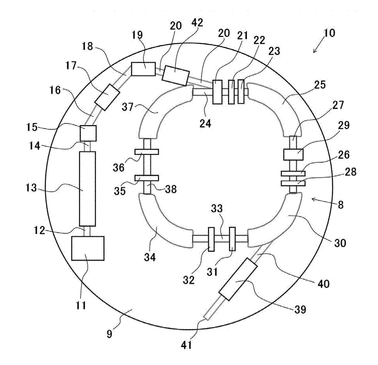
  • Ultra-compact mass analysis device and ultra-compact particle acceleration device
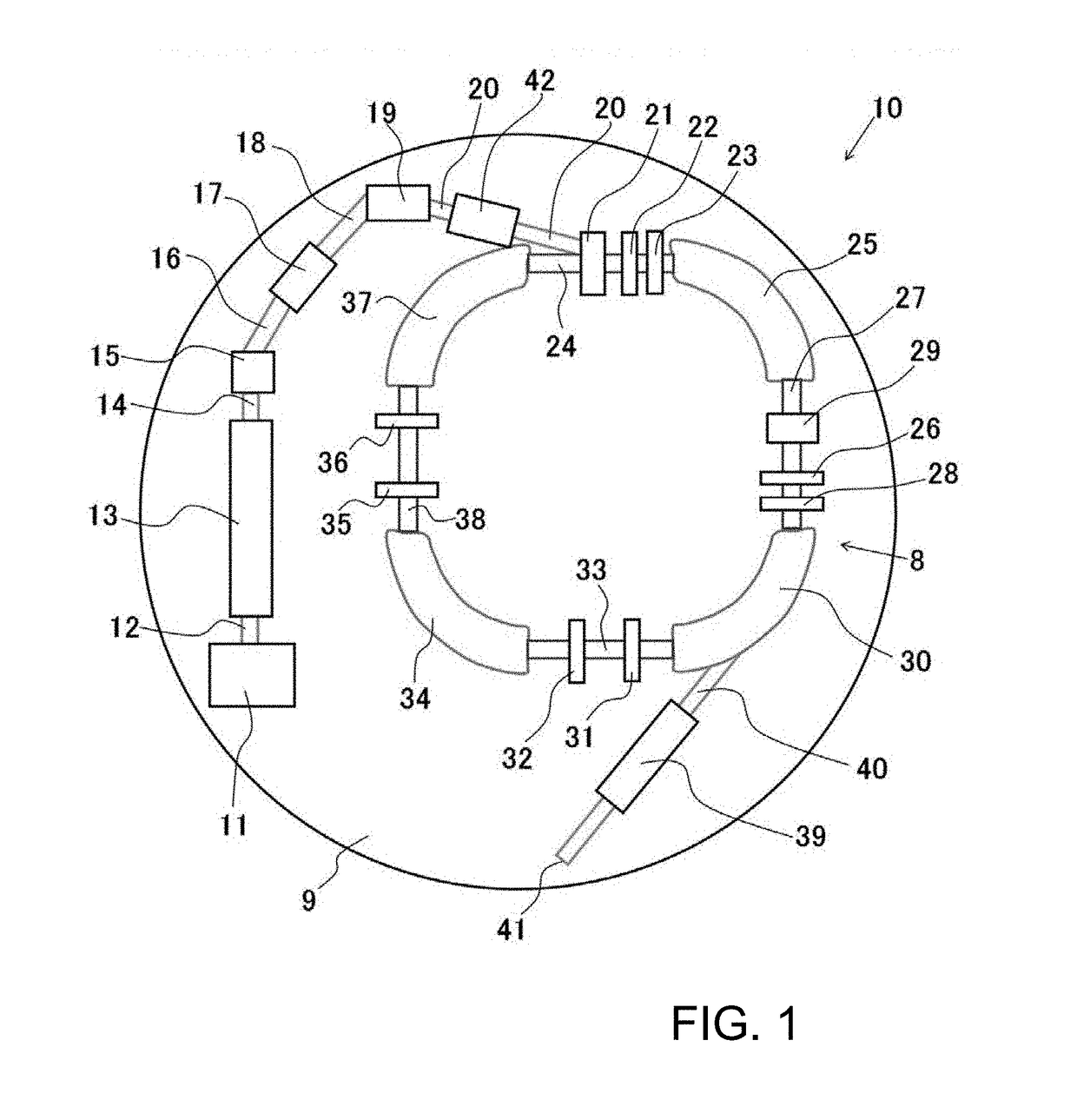
  • Ultra-compact mass analysis device and ultra-compact particle acceleration device
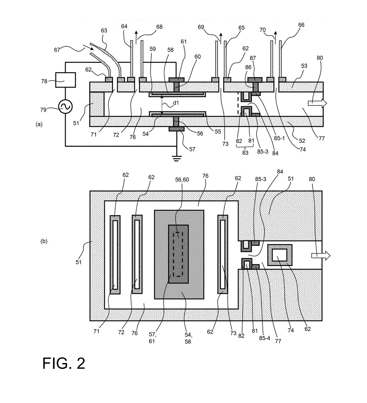
  • Ultra-compact mass analysis device and ultra-compact particle acceleration device

Examples


Embodiment Construction

[0081]In the present invention, a penetrated channel or a penetrated hole, which is written as “a penetrated cavity,” is formed in a thickness direction of a substrate or a thin plate, which is a main substrate or a first substrate, the present invention is an accelerator in which charged particles such as electrons or ions, etc. move in the cavity at very high speed. A substrate or a thin plate, which is a second substrate, on the cavity is attached on the top surface of the both side wall of the first substrate, and a substrate or a thin plate, which is a third substrate, under the cavity is attached underneath the bottom surface of the both side wall of the first substrate. Accordingly, since the top and bottom of the cavity are surrounded by the second and third substrates, and the both sides of the cavity are sandwiched between the side walls of the first substrate, the cavity is a airtight space. A part of or all of the second substrate, and / or a part of or all of the third su...


PUM


Abstract

A mass analyzer includes a main substrate, an upper substrate adhered to the main substrate, and a lower substrate. A mass analysis room (cavity) is formed in the main substrate and penetrates from an upper surface of the first main substrate to a lower surface of the first main substrate. A vertical direction (Z direction) to the main substrate by the upper substrate, both sides of the lower substrate, a travelling direction (X direction) of charged particles and a right angle to the Z direction by the main substrate, and both sides of a right-angled direction (Y to Z direction) and the X direction by a side surface of the main substrate are surrounded. A central hole is open in the side plate of the main substrate that the charged particles enter. The charged particles enter the mass analysis room through the central hole formed in the first main substrate.

Description

CROSS REFERENCE TO RELATED APPLICATIONS[0001]This application is a U.S. National Phase Application under 35 U.S.C. 371 of International Application No. PCT / JP2015 / 071538 filed on Jul. 29, 2015 and published in Japanese as WO 2016 / 017712 A1 on Feb. 4, 2016. This application claims the benefit of priority from Japanese Patent Application No. 2014-154005 filed Jul. 29, 2015. The entire disclosures of all of the above applications are incorporated herein by reference.TECHNICAL FIELD[0002]This invention is regarding an ultracompact mass spectroscope and an ultra small particle accelerator.BACKGROUND ART[0003]A particle accelerator is utilized in various fields such as a mass analysis, an atom smashing and molecular breakdown, and a generation of a radiation light. However, since high vacuum is needed in movement of particles, and a magnetic field generator and a electric field generator to generate large magnetic field or large electric field is needed, a particle accelerator is very lar...

Claims


Application Information

Patent Timeline
Patent Type & Authority Applications(United States)
IPC IPC(8): H01J49/06H01J49/20H01J49/22H01J49/42
CPCH01J49/06H01J49/4205H01J49/20H01J49/22G01N27/62H05H5/03H05H7/04H05H7/22H05H9/00H05H13/04H01J49/0018H01J49/326H01J49/38H01J49/4215
Inventor HOSAKA, TAKASHI
Owner HOSAKA TAKASHI
Learn More