
Method for vision-aided navigation for unmanned vehicles

a technology of unmanned vehicles and navigation methods, applied in the field of navigation, can solve the problems of inability to use gps, and inability to use gps, and achieve the effect of improving localization accuracy and improving accuracy

Active Publication Date: 2017-11-16
BAE SYST INFORMATION & ELECTRONICS SYST INTERGRATION INC
View PDF2 Cites 19 Cited by
  • Summary
  • Abstract
  • Description
  • Claims
  • Application Information

AI Technical Summary

Benefits of technology

The patent text describes an improved method for navigation that uses visual cues to guide vehicles. The method involves identifying faithful features in multiple images and creating a database with these features. Test images from actual vehicles are then registered against the database to estimate the vehicle's position and make corrections to its movement. This approach can provide more accurate navigation information, even in situations where current technology is not sufficient.

Problems solved by technology

For example, GPS may not always be available for various reasons.
In GPS-denied areas, GPS can be jammed making it unavailable or unreliable for navigation.
Even when GPS is available, signal occlusion or multipath effects in urban environments, often referred to as “urban canyons”, or in mountainous regions, can degrade GPS accuracy or provide coverage gaps.
Further, GPS signals can be weakened by meteorological conditions and by obstructed lines of sight arising from tree canopies, buildings, garages or tunnels.
Still further, the accuracy of GPS may be insufficient for autonomous vehicle navigation in some cases.
One drawback of an IMU guidance system is that the system continually adds detected changes to its previously-calculated positions (e.g. via dead reckoning).
If there are any errors in measurement, however small, they are accumulated point to point.
This leads to IMU ‘drift’ which is a continually-increasing difference between where the IMU guidance system reports it is located and the actual location of the IMU guidance system.
However, ‘noise’, or any undesired signal, in the accelerometer data leads to vehicle position error in the integrated position solution which can degrade the localization accuracy over time.

Method used


Image

  • Method for vision-aided navigation for unmanned vehicles
  • Method for vision-aided navigation for unmanned vehicles
  • Method for vision-aided navigation for unmanned vehicles

Examples


Embodiment Construction

[0053]Initially, the Inventors note that the present invention is a continuation-in-part application of U.S. patent application Ser. No. 15 / 004,029 (the '029 Application) filed on Jan. 22, 2016, the entirety of which is fully incorporated herein as if fully re-written. The present invention touches upon additional subject matter to the aforementioned '029 Application, namely, a method for vision-aided navigation. Since this is a continuation-in-part application of the '029 Application, some similar structural nomenclature is used herein when referencing some portions of the method for vision-aided navigation. However, there may be some instances where structural nomenclature differs between similar elements and there may be other instances where nomenclature is similar between distinct elements relative to this application and the '029 Application.

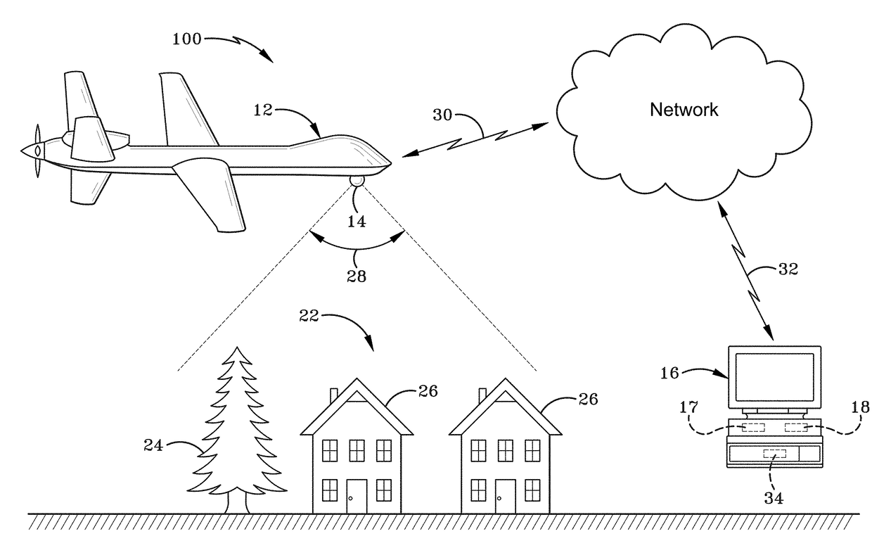
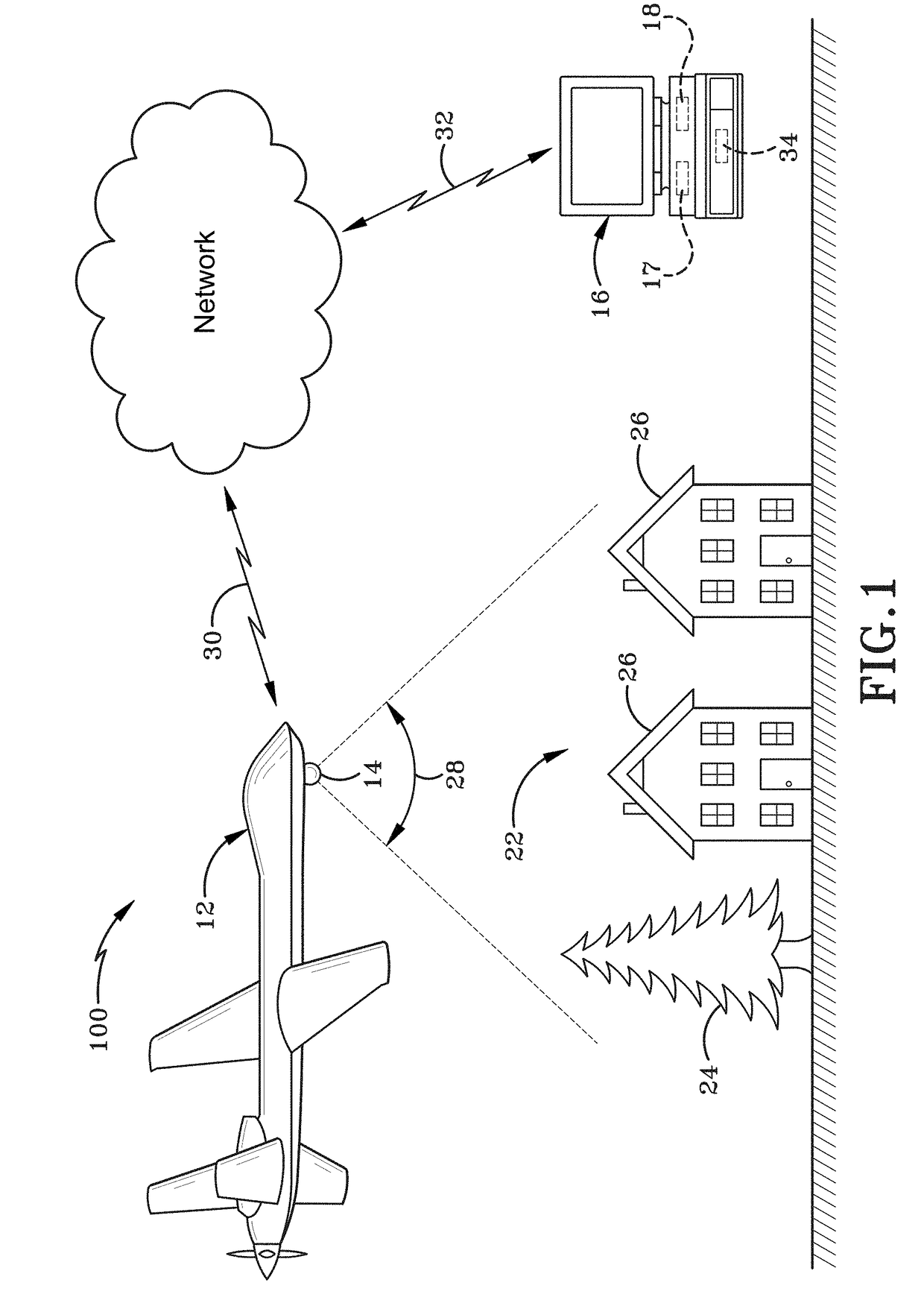
[0054]As depicted in FIG. 1, a vision-aided navigation system is broadly depicted as 100. Vision-aided navigation system 100 may include ...


PUM


Abstract

A method for vision-aided navigation which utilizes an image registration system to update a navigation control system. One exemplary feature of the method includes the use of Enhanced Phase Correlation techniques to create a reference imagery database and register images against the created database. The method may be operated on a non-transitory computer-readable medium storing a plurality of instructions which when executed by one or more processors causes the one or more processors to perform the method for vision-aided navigation which utilizes an image registration system to update a navigation control system.

Description

CROSS REFERENCE TO RELATED APPLICATIONS[0001]This application is a continuation-in-part patent application of prior copending U.S. patent application Ser. No. 15 / 004,029, filed Jan. 22, 2016, which application claims the benefit of U.S. Provisional Application Ser. No. 62 / 106,521, filed on Jan. 22, 2015; the disclosures of which are entirely incorporated herein by reference as if fully rewritten.STATEMENT OF GOVERNMENT INTEREST[0002]This disclosure was made with United States Government support under Contract No. FA8650-04-C-1675 awarded by the Department of the Air Force. The United States Government has certain rights in this invention.BACKGROUND OF THE INVENTIONTechnical Field[0003]The present disclosure relates generally to navigation. More particularly, the present disclosure relates to navigation of aerial and ground-based vehicles. Specifically, the present disclosure relates to a method for vision-aided navigation which utilizes an image registration system to update navigat...

Claims


Application Information

Patent Timeline
IPC IPC(8): G05D1/02G06F17/30G06T7/30G01C21/00G06T7/70G05D1/10B64C39/02G06V10/42G06V20/13
CPCG05D1/02G06T7/30G06T7/70G06F17/30256G06F17/3028G01C21/005G05D1/10B64C39/024G05D1/101G06T2200/28G06T7/32G06F16/51G06F16/5838G06V20/13G06V10/42B64U10/14B64U2101/30
Inventor DELMARCO, STEPHEN P.TOM, VICTOR T.
Owner BAE SYST INFORMATION & ELECTRONICS SYST INTERGRATION INC
Learn More