
Method for generation of synthetic mammograms from tomosynthesis data

a tomosynthesis and mammogram technology, applied in image data processing, instruments, computing, etc., can solve the problems of yet another radiation dosage exposure, and achieve the effects of enhancing the image structure, facilitating computation, and improving the visible quality

Active Publication Date: 2017-11-02
KONINKLJIJKE PHILIPS NV
View PDF8 Cites 19 Cited by
  • Summary
  • Abstract
  • Description
  • Claims
  • Application Information

AI Technical Summary

Benefits of technology

The patent describes a technique for enhancing the visibility of certain image structures in a second image by using information from a first image. This is done by computing a weight function based on the first image and applying it to the second image. The weight function can be re-sampled to match the sampling of the second image. The technique can be used for multiple images and provides a more efficient way to compute the weight function. The image elements can be individual voxels or elements of a coarser partition of the volume, with the size of the elements adjusted for different requirements. The technical effect is improved visibility of certain image structures in a second image.

Problems solved by technology

However, this comes at the expense of yet another radiation dosage exposure.

Method used


Image

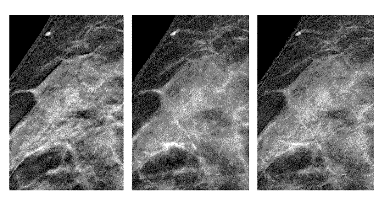
  • Method for generation of synthetic mammograms from tomosynthesis data
  • Method for generation of synthetic mammograms from tomosynthesis data
  • Method for generation of synthetic mammograms from tomosynthesis data

Examples


Embodiment Construction

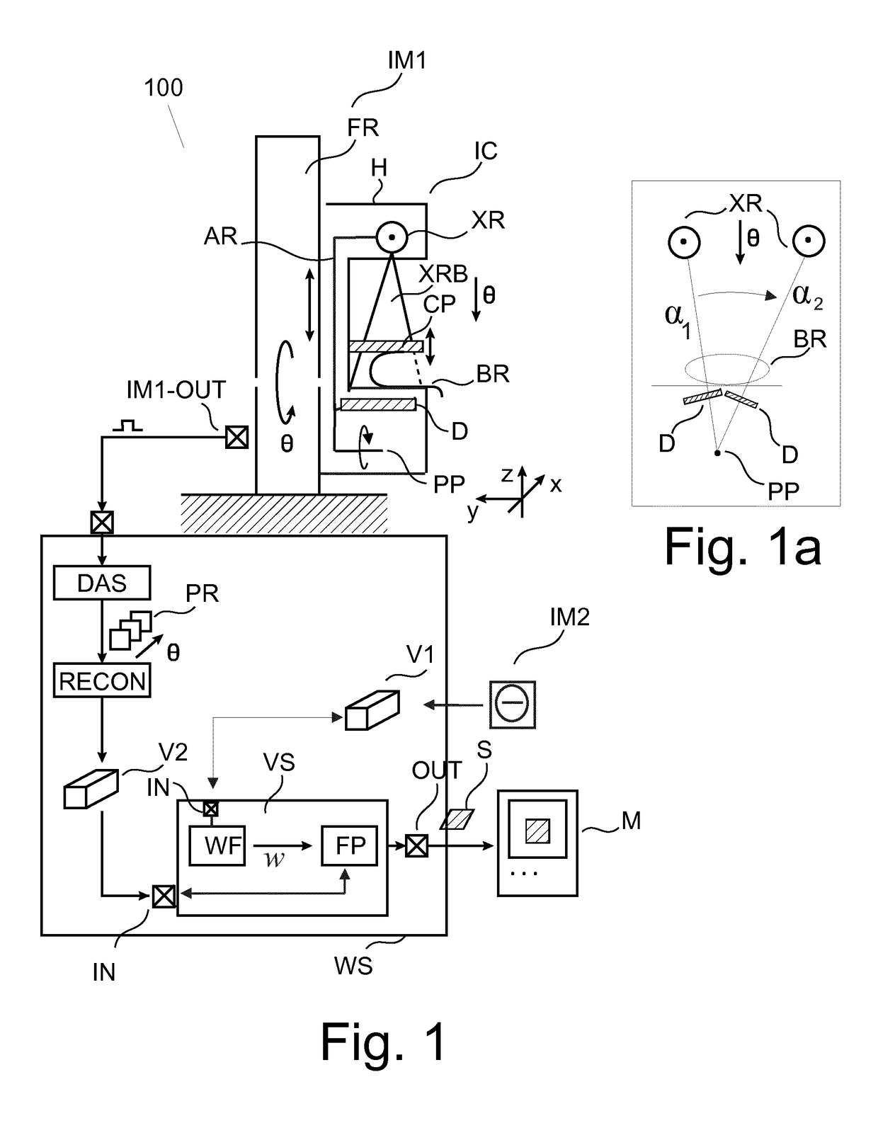
[0031]With reference to FIG. 1, there is shown an imaging arrangement 100. The arrangement 100 comprises in one embodiment an imaging modality IM1 such as a (3D) tomosynthesis mammography imaging scanner (MIS) (also referred to herein more generally as the “imager”) and a workstation WS for controlling operation of MIS. Although the imaging modality IM1 is explained in some detail below, other (types) of imaging modalities are also envisaged instead, such as CT (computed tomography) scanner, MRT etc.

[0032]The MIS includes a frame FR which is either wall mounted or freestanding. On said frame FR, a rigid imager carriage IC is mounted so as to be slidable along a vertical axis y. The imager carriage is energizable by a suitable actuator-controller arrangement for precise positioning along said axis to so accommodate the imaging system to height requirements of a patient whose breast BR is to be imaged.

[0033]The imager carriage IC includes a movable arm (or “gantry”) AR on one, upper e...


PUM


Abstract

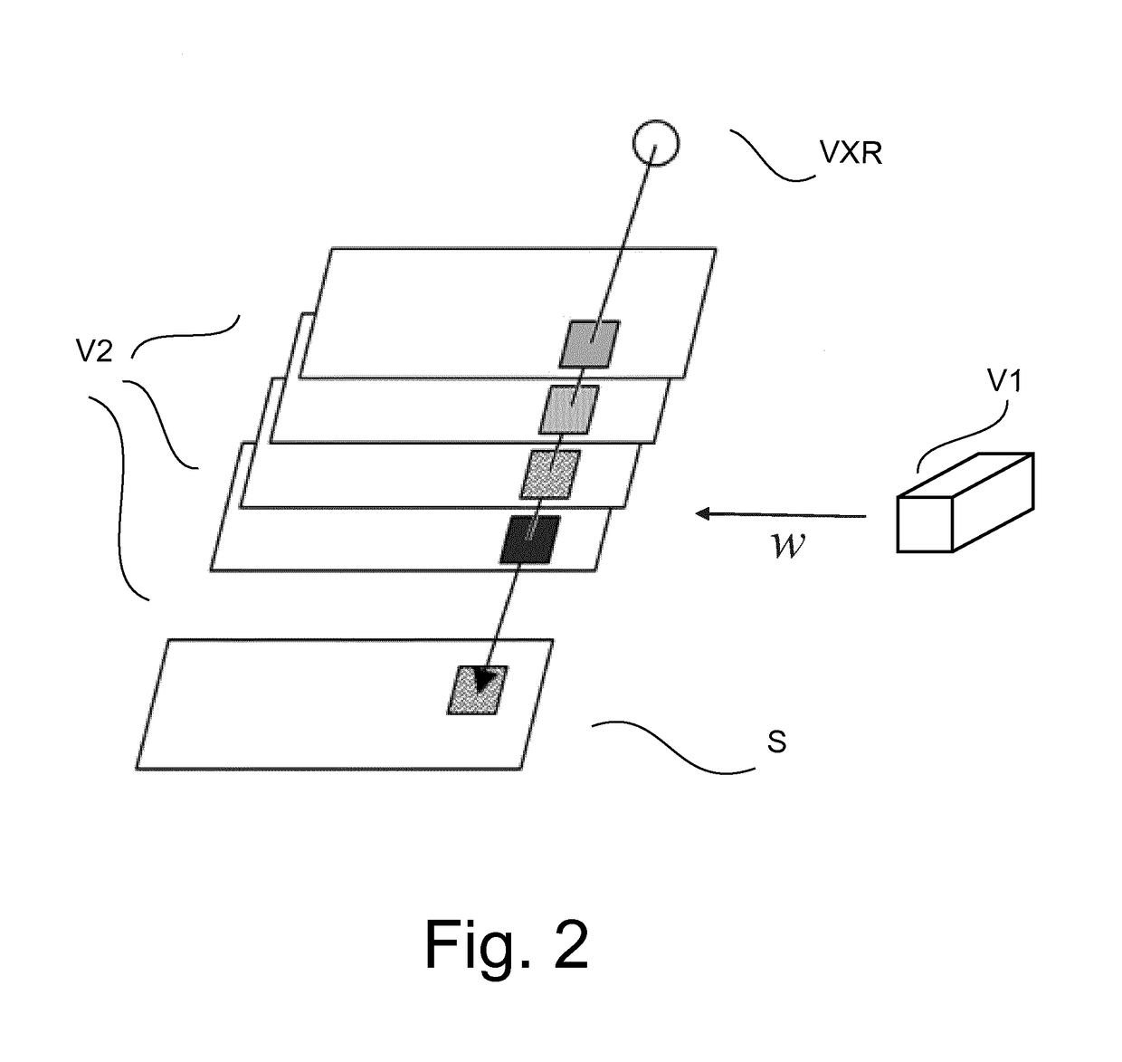
A method and related apparatus (VS) for synthesizing a projection image (S), in particular for use in mammography. It is proposed to compute a weight function from one image volume (V1) and is then used to implement a weighted forward projection through another image volume block to compute a synthesized projection image (S) across block (V2).

Description

FIELD OF THE INVENTION[0001]The invention relates to an image processing method, to an image processing apparatus, to a mammography imaging system, to a computer program element, and to a computer readable medium.BACKGROUND OF THE INVENTION[0002]In X-ray tomosynthesis, multiple X-ray projections (for instance, mammograms) from different angles are acquired and computationally combined into a 3D tomographic image volume.[0003]Typically, at least one conventional 2D mammogram is also acquired as a reference image. However, this comes at the expense of yet another radiation dosage exposure.[0004]Another option is to use a computational method to generate a “synthetic” mammogram view from the available 3D tomographic image volume.[0005]A method to compute synthetic mammograms is based on the maximum-intensity-projection (MIP) approach and is described in U.S. Pat. No. 7,760,924.SUMMARY OF THE INVENTION[0006]There may be a need for an alternative method and related apparatus to compute a...

Claims


Application Information

Patent Timeline
IPC IPC(8): G06T11/00
CPCG06T11/008G06T2210/41G06T2211/408G06T2211/464
Inventor HOMANN, HANNO HEYKEERHARD, KLAUS
Owner KONINKLJIJKE PHILIPS NV
Learn More