Light effect control

Active Publication Date: 2017-10-26
SIGNIFY HLDG BV
View PDF0 Cites 9 Cited by
  • Summary
  • Abstract
  • Description
  • Claims
  • Application Information

AI Technical Summary

Benefits of technology

The invention provides a method for a computer program to control the rendering of light effects through a networked lighting system. The method allows the application to determine the type of event it is receiving and the capacity of the lighting system to execute a control command. It then selects between two scenarios: one for dismissing the event and another for executing the control command. This helps to prevent overload of the system and ensures that events with a high impact on the user experience are prioritized. The method can be embedded in a hardware device or a lighting engine and improves the reliability and predictability of the networked lighting system.

Problems solved by technology

Although such modern lighting systems offer advantages, they are far more complex than traditional lighting systems from a controls perspective.
Such complexity can introduce undesired effects, such as unpredictability related to the execution of lighting control commands and rendering of related light effects.

Method used


Image

  • Light effect control
  • Light effect control
  • Light effect control

Examples


Embodiment Construction

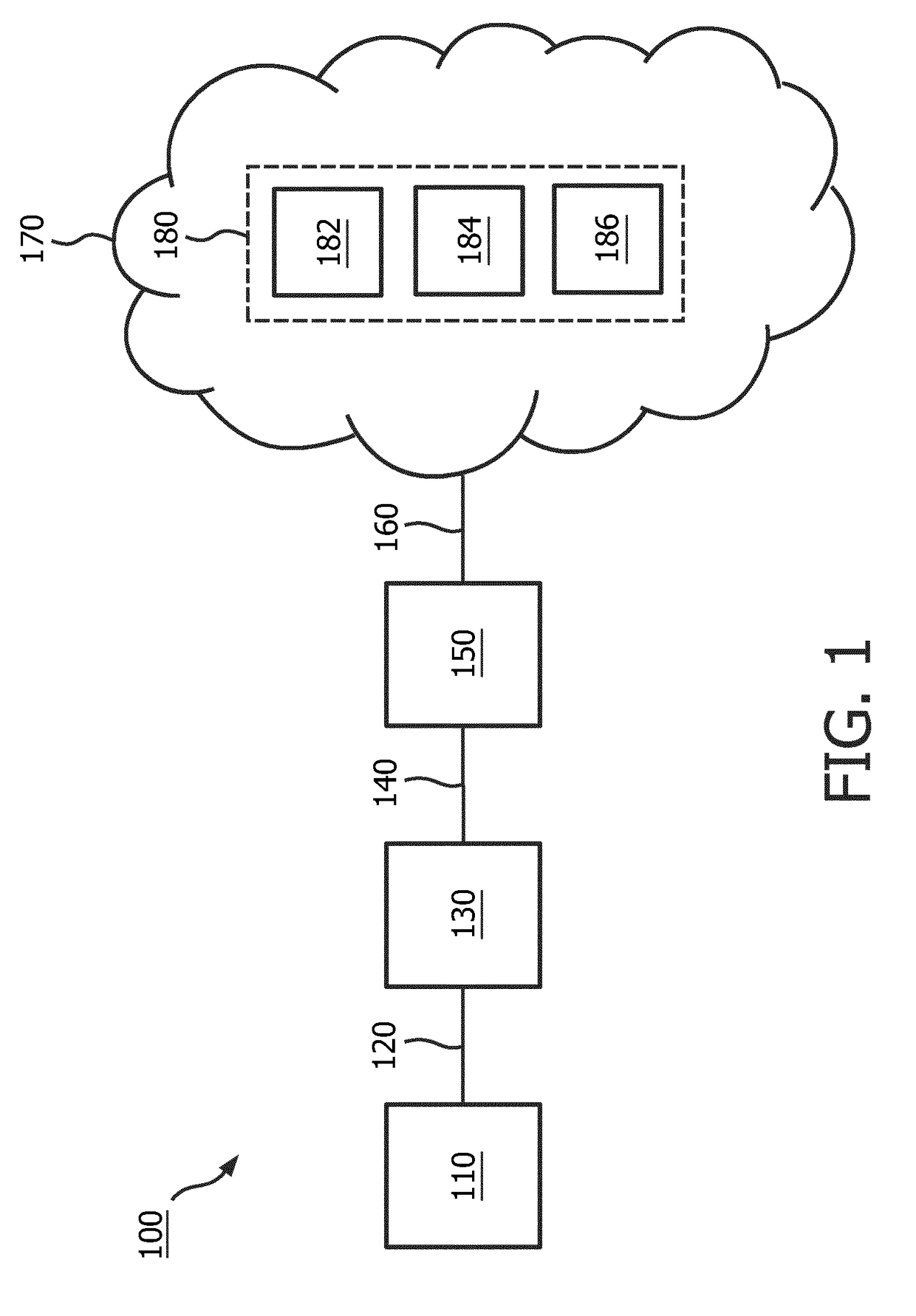
[0024]In FIG. 1 an overview 100 is provided showing a game engine 110 arranged for interfacing over a game engine to game code interface 120 with game code 130, the game code 130 further interfaced over a game code to lighting engine interface 140 to a lighting engine 150. The lighting engine 150 is further arranged for interfacing over a network interface 160 to a network 170 comprising a lighting system 180. The lighting system, in this example, comprising various lighting system devices 182, 184, 186. As an example, the game code 130 can initiate an action to be executed by the game engine 110 by calling a routine over the interface 120 that causes movement of a character in the video output of a computer game and initiate an action to be executed by the lighting engine 150 by using an API offered by the lighting engine 150 over the interface 140 that is intended to create a light effect rendered by at least one lighting system device 182, 184, 186 in the lighting system 180. The...


PUM


Abstract

A light effect control method, computer program product and device are presented which allow an application to render a light effect by a networked lighting system based on the method, computer program product or device receiving an event being from the application. To provide a better user experience, light effects related to certain events need to be rendered even if a delay in rendering is expected whereas light effects related to other events need to be rendered without delay or else not rendered at all. As such, a decision is made to execute a first or a second scenario based on the event type of the event received and / or the capacity of the networked lighting system, wherein in the first scenario the lighting control command is always sent to the networked lighting system and in the second scenario the lighting control command is only sent to the networked lighting system if no unacceptable delay in rendering the light effect is expected.

Description

FIELD OF THE INVENTION[0001]The present invention relates to methods for light effect control and more in particular to a computer implemented method for allowing an application to render a light effect via a networked lighting system. The present invention further relates to control devices for light effect control and more in particular to a networked lighting system control device for controlling a lighting device in a networked lighting system.BACKGROUND OF THE INVENTION[0002]Traditional lighting systems are typically stand-alone systems that offer on / off or dim-level control of a single color of light (e.g. white) via a physical switch. Recent developments have led to modern lighting systems that, for example, can emit various colors and can be controlled over a wireless network using a smart phone. Although such modern lighting systems offer advantages, they are far more complex than traditional lighting systems from a controls perspective. As an example, when in a traditional...

Claims


Application Information

Patent Timeline
IPC IPC(8): H05B37/02A63F13/85A63F13/327H04L29/08
CPCH05B37/0227H05B37/0272H04L67/12A63F13/85A63F13/327H05B47/105H04L12/2803H04W28/0231H05B47/115H05B47/19Y02B20/40A63F13/216A63F13/235A63F13/25A63F13/28
Inventor ROZENDAAL, LEENDERT TEUNISHUBBERS, ALOYS
Owner SIGNIFY HLDG BV
Why Eureka
Try Eureka