Dropping rate measuring device, dropping rate controller, drip infusion device, and liquid droplet volume measuring device
a technology of dropping rate and measuring device, which is applied in the direction of other medical devices, process and machine control, instruments, etc., can solve the problems of high-speed image processing capability and expensive cameras, and achieve the effect of accurately measuring the flow rate regardless
- Summary
- Abstract
- Description
- Claims
- Application Information
AI Technical Summary
Benefits of technology
Problems solved by technology
Method used
Image
Examples
first embodiment
[0124]
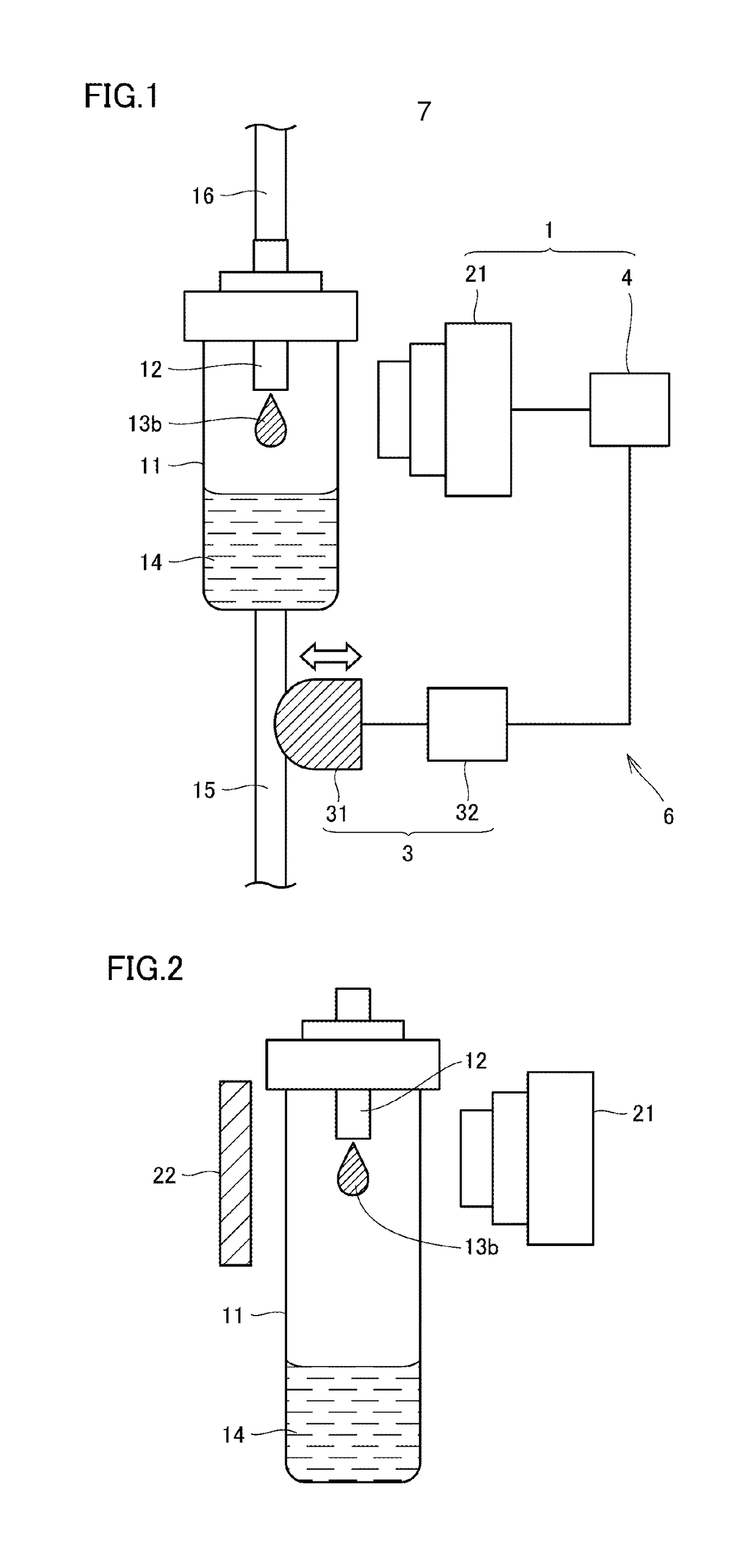
[0125]A drip infusion device 7 in the embodiment mainly includes a drip infusion cylinder 11, a nozzle 12 for causing liquid droplets to intermittently drop in the drip infusion cylinder 11, a tube 15 for discharging the liquid droplets which have dropped in the drip infusion cylinder 11 from the drip infusion cylinder 11, and a dropping rate controller 6 with reference to FIG. 1. It should be noted that the dropping rate controller 6 will be described in detail later.
[0126]The nozzle 12 (dropping nozzle) for causing liquid droplets 13 to intermittently drop is provided in an upper portion of the drip infusion cylinder 11. The inside of the nozzle 12 communicates with the inside of the drip infusion cylinder 11.
[0127]The drip infusion cylinder 11 is arranged at, for example, a halfway position on a transfusion line to a patient from a transfusion bag hung by a stand at a higher position than the patient. The upper end of the nozzle 12 is connected to a tube 16 configuring the ...
second embodiment
[0182]The embodiment is different from the first embodiment in a point that in a dropping rate measuring device, a data processor analyzes pieces of image data to directly calculate a volume increase speed of a growing liquid droplet without necessarily counting the number of times of dropping and sets the volume increase speed as a flow rate.
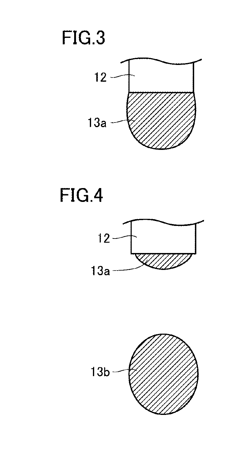
[0183]In the first embodiment, as described above by referring to FIG. 10, the volumes of the liquid droplet 13a can be calculated from the two-dimensional images (regions surrounded by the contours 43) in the respective pieces of image data.
[0184]The volume of the liquid droplet 13a that has adhered to the lower end of the nozzle 12 is largely decreased after the liquid droplet drops. Therefore, one cycle from dropping to subsequent dropping can be cut out from a series of pieces of image data. Among the series of pieces of image data cut out as one cycle from the dropping to the subsequent dropping, the respective volumes of the liquid drople...
third embodiment
[0191]The embodiment is different from the first embodiment and the second embodiment in a point that operation of the imaging unit 21 is stopped after the estimated volume of at least one dropping liquid droplet is calculated.
[0192]The volume of each dropping liquid droplet is stable as long as the type of the liquid droplets (transfusion) and the shape, the material, and the like of the nozzle are the same. Therefore, after the volume of one dropping liquid droplet is grasped using the imaging unit 21 (camera) initially, the flow rate can be measured by operating only the count unit (dropping detecting unit) while stopping (suspending) the operation of the imaging unit 21 to reduce power consumption. With this, in the embodiment, the power consumption can be reduced in comparison with the case in which the imaging unit 21 is operated all the time.
[0193]FIG. 15 illustrates a schematic graph plotted while the longitudinal axis is set to the volume of the liquid droplet in each image...
PUM
 Abstract
Description
Claims
Application Information
 - R&D
- Intellectual Property
- Life Sciences
- Materials
- Tech Scout
- Unparalleled Data Quality
- Higher Quality Content
- 60% Fewer Hallucinations
Browse by: Latest US Patents, China's latest patents, Technical Efficacy Thesaurus, Application Domain, Technology Topic, Popular Technical Reports.
© 2025 PatSnap. All rights reserved.Legal|Privacy policy|Modern Slavery Act Transparency Statement|Sitemap|About US| Contact US: help@patsnap.com


