Flexible scanner resistant device emulating a banknote for protection of RFID cards

a scanner-resistant device and banknote technology, applied in the field of electronic commerce, can solve the problems of limiting the use of the device, not allowing easy flexing or bending of the device, and the rfid technology, so as to prevent prevent the radio frequency scanning of the card, and improve the use

Inactive Publication Date: 2017-10-26
COHEN ERIC +1
View PDF3 Cites 0 Cited by
  • Summary
  • Abstract
  • Description
  • Claims
  • Application Information

AI Technical Summary

Benefits of technology

[0010]Briefly, according to an embodiment, a device for protecting one or more credit or charge cards from radio frequency scanning is disclosed. The device comprises a rectangular-shaped planar element sized for fitting within the banknote slot of a personal carrying accessory, wherein the planar element is composed of a top layer of plastic material having an interior surface including printed information, a middle layer of a metallic foil that inhibits the transmission of radio frequency signals, and a bottom layer of plastic material having an interior surface including printed information, wherein the top layer and the bottom layer of plastic material completely cover a surface area of both sides of the middle layer, and wherein the device has a thickness of about 0.3 mm and exhibits a bending stiffness substantially equal to paper.
[0011]In another embodiment, method for preventing radio frequency scanning of a card is disclosed. The method includes placing a first rectangular-shaped planar element within a banknote slot of a personal carrying case such that the first planar element is located substantially around one or more cards within the personal carrying case, wherein the planar element is sized for fitting within a banknote slot of the personal carrying case, wherein the planar element is substantially from about 7 and ¾ inches in length, to about 2 and ⅞ in width, and wherein the planar element is composed of a top layer of plastic material having an interior surface including printed information, a middle layer of a metallic foil that inhibits the transmission of radio frequency signals, and a bottom layer of plastic material having an interior surface including printed information, wherein the top layer and the bottom layer of plastic material completely cover a surface area of both sides of the middle layer.
[0012]In another embodiment, system for preventing radio frequency scanning of a card is disclosed. The system includes a personal carrying case comprising a plurality of card slots for inserting cards and a banknote slot for inserting banknotes; at least one card including information that may be scanned via a radio frequency scanner, wherein said at least one card is inserted into the plurality of card slots; and a rectangular-shaped planar element sized for fitting within the banknote slot of the personal carrying accessory, wherein the planar element is composed of a top layer of plastic material having an interior surface including printed information, a middle layer of a metallic foil that inhibits the transmission of radio frequency signals, and a bottom layer of plastic material having an interior surface including printed information, wherein the top layer and the bottom layer of plastic material completely cover a surface area of both sides of the middle layer, and wherein the device has a thickness of about 0.3 mm and exhibits a bending stiffness substantially equal to paper.

Problems solved by technology

RFID technology, however, has come with drawbacks.
But the device of U.S. Pat. No. 8,578,982 is rigid and does not allow for easy flexing or bending of the device.
This limits the use of the device and lowers consumers' desires to utilize the device.

Method used


Image

  • Flexible scanner resistant device emulating a banknote for protection of RFID cards
  • Flexible scanner resistant device emulating a banknote for protection of RFID cards
  • Flexible scanner resistant device emulating a banknote for protection of RFID cards

Examples


Embodiment Construction

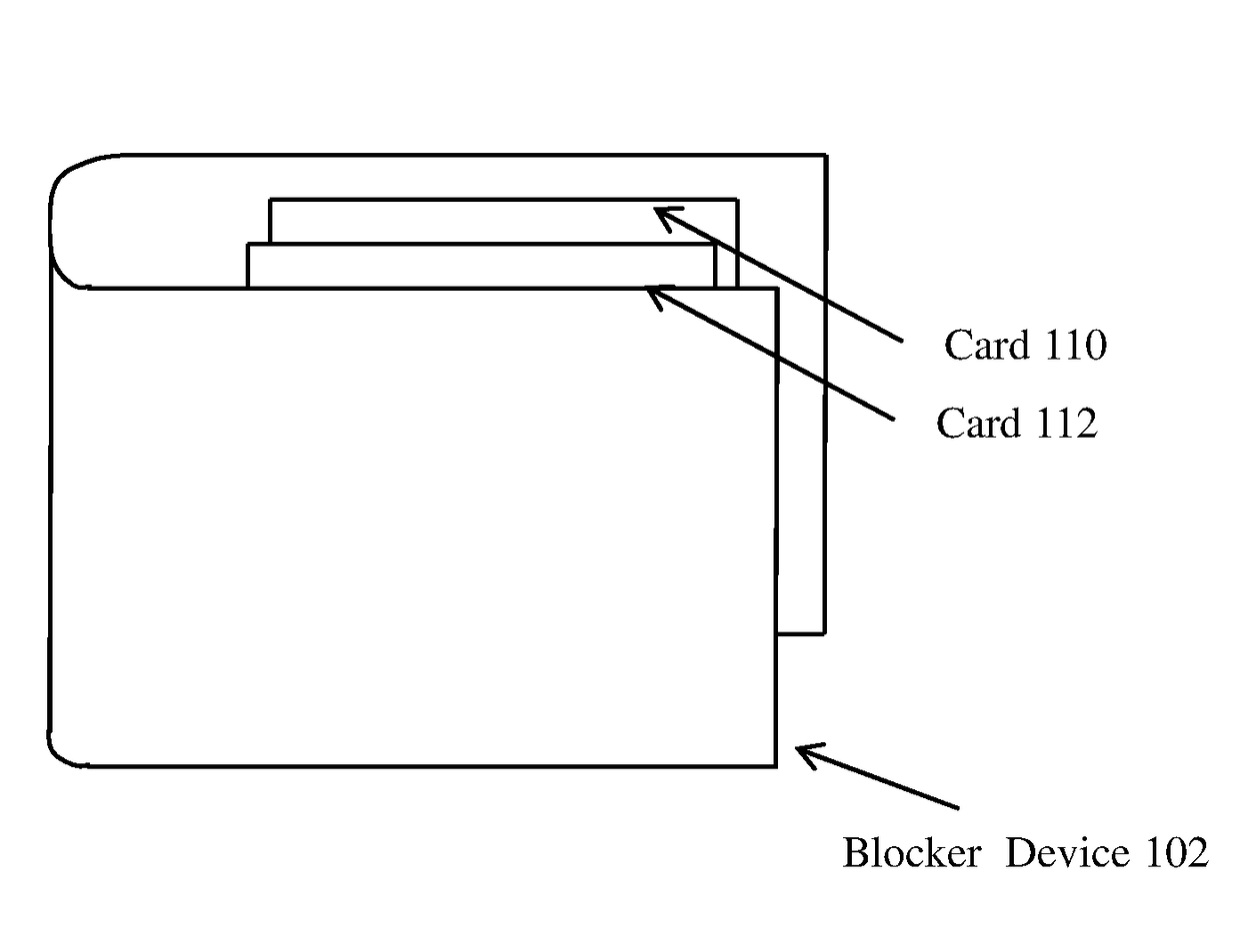
[0022]The claimed subject matter solves the problems with the prior art by providing a small, inexpensive and lightweight device that prevents surreptitious scanning of RFID cards and that can be placed within an existing personal carrying case, such as a wallet, purse, handbag, holder or other type of carrying device. RFID cards that may be protected include credit cards, charge cards, identification cards, security tokens, pass cards, entry cards, passports, badges, etc. The claimed subject matter is advantageous since it allows for the use of existing personal carrying cases and does not require the purchase of new carrying cases that prevent scanning. The claimed subject matter is further advantageous since it is manufactured from lightweight, durable material that remains effective for extended periods of time. Also, the claimed subject matter is advantageous since it allows for easy flexing or bending of the device. This increases the utility of the device.

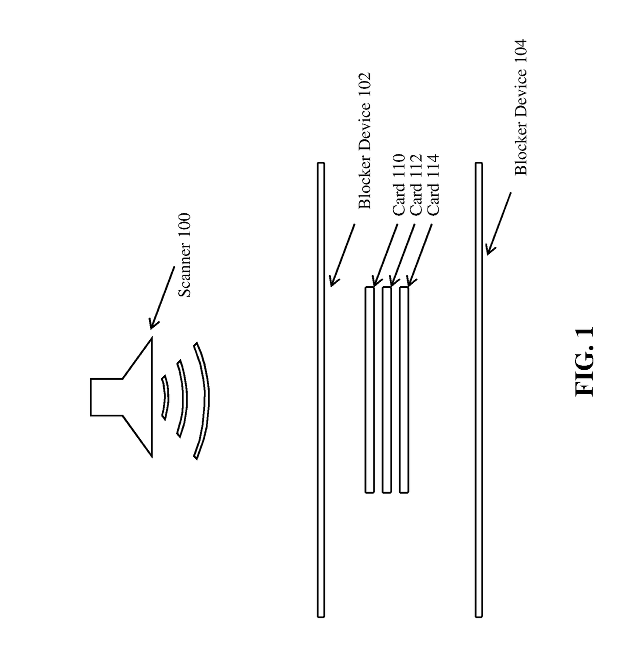
[0023]FIG. 1 is an i...


PUM


Abstract

A device for protecting one or more credit or charge cards from radio frequency scanning is disclosed. The device comprises a rectangular-shaped planar element sized for fitting within the banknote slot of a personal carrying accessory, wherein the planar element is composed of a top layer of plastic material having an interior surface including printed information, a middle layer of a metallic foil that inhibits the transmission of radio frequency signals, and a bottom layer of plastic material having an interior surface including printed information, wherein the top layer and the bottom layer of plastic material completely cover a surface area of both sides of the middle layer, and wherein the device has a thickness of about 0.3 mm and exhibits a bending stiffness substantially equal to paper.

Description

CROSS-REFERENCE TO RELATED APPLICATIONS[0001]Not Applicable.STATEMENT REGARDING FEDERALLY SPONSORED RESEARCH OR DEVELOPMENT[0002]Not Applicable.INCORPORATION BY REFERENCE OF MATERIAL SUBMITTED ON A COMPACT DISC[0003]Not Applicable.TECHNICAL FIELD[0004]The claimed subject matter disclosed broadly relates to the field of electronic commerce, and more particularly relates to the field of security as it relates to RFID cards used in electronic commerce.BACKGROUND[0005]Radio-frequency identification (RFID) is a technology that uses radio waves to transfer data from an electronic tag, called an RFID tag or label, attached to an object, through a reader for the purpose of identifying and tracking the object. RFID technology has been used for many applications, including key entry cards, passports, road toll fee payments, identification cards, and cash transaction cards, such as credit and charge cards. RFID technology typically includes embedding a card or device with a microchip that stor...

Claims


Application Information

Patent Timeline
Patent Type & Authority Applications(United States)
IPC IPC(8): A45C1/06A45C11/18
CPCA45C1/06A45C2011/186A45C2001/065A45C11/182
Inventor COHEN, ERICLEE, VICTOR
Owner COHEN ERIC
Why Eureka
Try Eureka