
Method for producing TFT array substrate, TFT array substrate, and display apparatus

a technology of thin film transistors and array substrates, applied in the field of display, can solve the problems of increasing the power consumption of tft array substrates, no signal transmission, and tending to drain signal lines

Active Publication Date: 2017-10-19
BOE TECH GRP CO LTD +1
View PDF5 Cites 1 Cited by
  • Summary
  • Abstract
  • Description
  • Claims
  • Application Information

AI Technical Summary

Benefits of technology

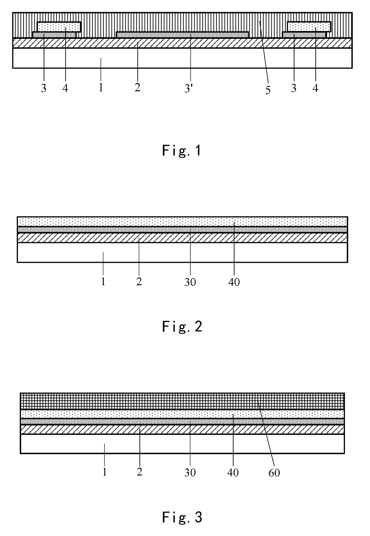
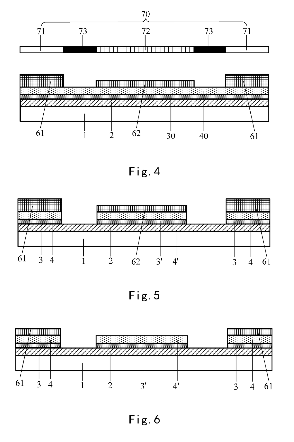
The present application provides a method for producing a TFT array substrate and a display apparatus that can solve the problem of no signal transmission due to the fracture of the source signal line without increasing the coupling capacitance. The method involves overlapping the source signal line and the pixel electrode line, and when the source signal line is fractured, the signal can be conducted by the pixel electrode line below the fractured source signal line. Additionally, the source signal line and the pixel electrode line are formed by the same one patterning process, which prevents alignment deviation and ensures they exactly overlap with each other and have no misplacement, thereby maintaining the width of the source signal line and not increasing the coupling capacitance with the pixel electrode line. The display apparatus includes this TFT array substrate, which also solves the problem of no signal transmission due to the fracture of the source signal line.

Problems solved by technology

Due to influences caused by factors such as a preceding process and a following process of the patterning process for the source-drain metal layer, and non-uniformity of coating of photoresist in the patterning process of the source-drain metal layer, the source-drain signal line tends to be fractured, resulting in no signal transmission.
However, in an actual application of the above improved technical solution, this will cause the coupling capacitance of the TFT array substrate to increase, resulting in increase of power consumption of the TFT array substrate.

Method used


Image

  • Method for producing TFT array substrate, TFT array substrate, and display apparatus
  • Method for producing TFT array substrate, TFT array substrate, and display apparatus
  • Method for producing TFT array substrate, TFT array substrate, and display apparatus

Examples


Embodiment Construction

[0024]As described in the background part, the technical solution in the prior art that the pixel electrode line 3 is disposed below the source signal line 4, cannot well solve the problem of no signal transmission caused by the fracture of the source signal line 4.

[0025]Through amount of research and experiments, it is found that the main reason for the above problem is the pixel electrode line 3 and the source signal line 4 respectively formed in two patterning processes. In the patterning process of the source-drain metal layer, it is necessary for the reticle to align with the pixel electrode line 3. Due to limitation of the patterning process, it tends to generate deviation upon aligning. This causes the formed source signal line 4 not to overlap the pixel electrode line 3 exactly, and there is misplacement between them. This will be equivalent to increasing a width of the source signal line 4, thereby causing reduction of a spacing between the source signal line 4 and the pixe...


PUM


Abstract

The present disclosure provides a method for producing a TFT array substrate, a TFT array substrate, and a display apparatus, and relates to a technical field of display. It can solve a problem of no signal transmission caused by fracture of a source signal line, without increasing a coupling capacitance of the TFT array substrate. The method for producing a TFT array substrate includes: forming a transparent conductive layer and a source-drain metal layer in sequence onto a base substrate; and patterning the source-drain metal layer and the transparent conductive layer in one patterning process to form a source signal line and a pixel electrode line overlapping with each other.

Description

CROSS-REFERENCE TO RELATED APPLICATION[0001]This application is a Section 371 National Stage Application of International Application No. PCT / CN2016 / 072292, filed on Jan. 27, 2016, entitled “METHOD FOR PRODUCING TFT ARRAY SUBSTRATE, TFT ARRAY SUBSTRATE, AND DISPLAY APPARATUS”, which has not yet published, and which claims priority to Chinese Application No. 201510605434.9, filed on Sep. 21, 2015, incorporated herein by reference in their entirety.BACKGROUND OF THE DISCLOSUREField of the Disclosure[0002]The present disclosure relates to a technical field of display, more particularly, to a method for producing a TFT (Thin Film Transistor) array substrate, a TFT array substrate, and a display apparatus.Description of the Related Art[0003]A TFT array substrate is an important integral part of a display apparatus. The TFT array substrate normally includes a base substrate, and a gate electrode, a gate protection layer, an active layer, a pixel electrode, a source electrode, a drain elec...

Claims


Application Information

Patent Timeline
Patent Type & Authority Applications(United States)
IPC IPC(8): H01L27/12
CPCH01L27/1244H01L27/127H01L27/1288H01L27/124H01L27/1259
Inventor CHEN, LEIPENG, ZHILONGDAI, WUKUNZHANG, LEIQIU, MIAO
Owner BOE TECH GRP CO LTD
Learn More