
Compressor

a compressor and impeller technology, applied in the field of compressors, can solve the problems of unstable flow of compressed air out of the compressor impeller into the fixed diffuser, and decrease in supercharging efficiency,

Inactive Publication Date: 2017-10-19
HONDA MOTOR CO LTD
View PDF6 Cites 18 Cited by
  • Summary
  • Abstract
  • Description
  • Claims
  • Application Information

AI Technical Summary

Benefits of technology

The patent text discusses a compressor with a blade that has a semi-elliptic cylindrical shape at the trailing edge. This design helps improve the efficiency of supercharging by preventing the fluid from separating at that point.

Problems solved by technology

However, there is a trade-off relationship between the blade strength and the aerodynamic performance of the compressor impeller.
Loss is caused by the thickness of the blade creating a limit to the above adjustment.
Meanwhile, cutting off (cutback) of the trailing edge of the blade of the compressor impeller has been performed; however, in such a case, the compressed air flowing out from the compressor impeller flows into the fixed diffuser in an unstable state.
Accordingly, as a result of decrease in the static pressure efficiency at the compressor impeller outlet, a problem of decrease in supercharging efficiency occurs.

Method used


Image

  • Compressor
  • Compressor
  • Compressor

Examples


Embodiment Construction

[0020]The embodiment(s) will now be described with reference to the accompanying drawings, wherein like reference numerals designate corresponding or identical elements throughout the various drawings.

[0021]Hereinafter, an exemplary embodiment of the present disclosure will be described with reference to the drawings.

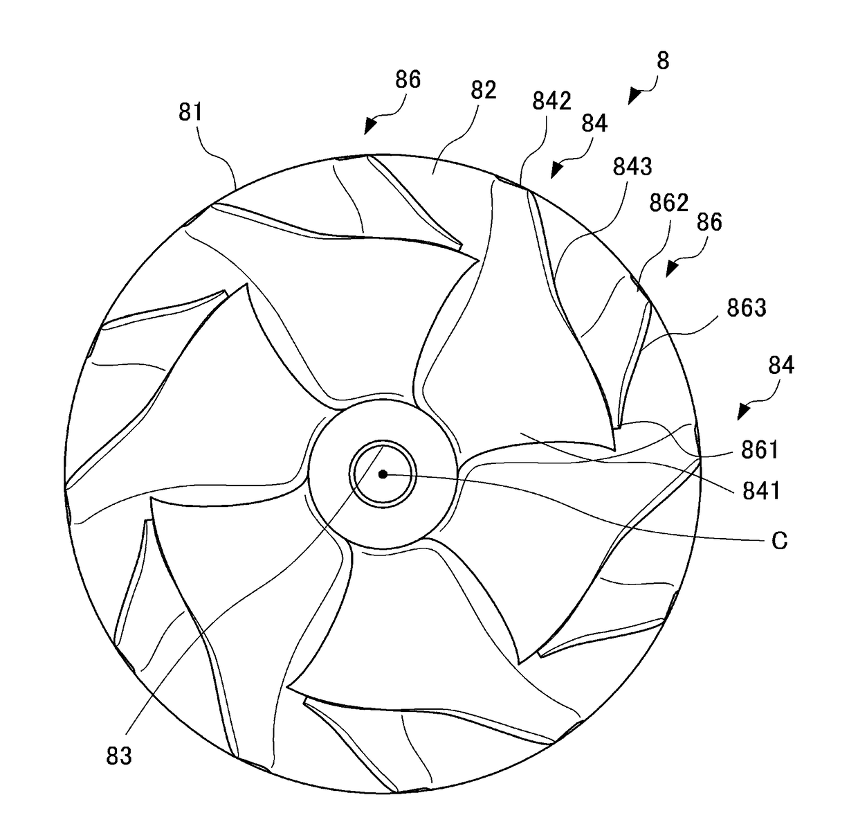
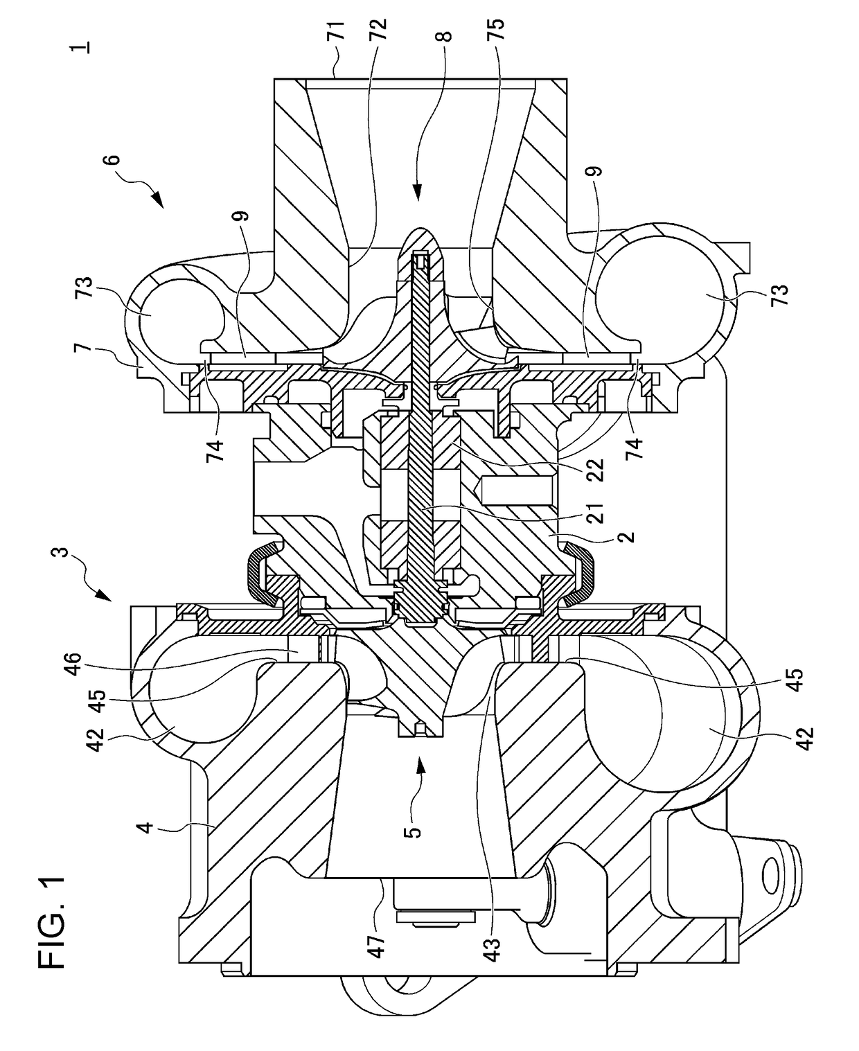
[0022]FIG. 1 is a cross-sectional view illustrating a configuration of a supercharger 1 using a compressor according to the present exemplary embodiment.

[0023]The supercharger 1 includes a turbine 3 mounted on one end of the bearing housing 2, and a compressor 6 mounted on the other end of the bearing housing 2. The bearing housing 2 includes a rod-shaped rotating shaft 21 extending between the turbine 3 and compressor 6, and a bearing 22 that rotatably supports the rotating shaft 21.

[0024]The turbine 3 includes a turbine housing 4 constituting a portion of an exhaust passage of an internal-combustion engine (not shown), and a turbine impeller 5 provided inside the turb...


PUM


Abstract

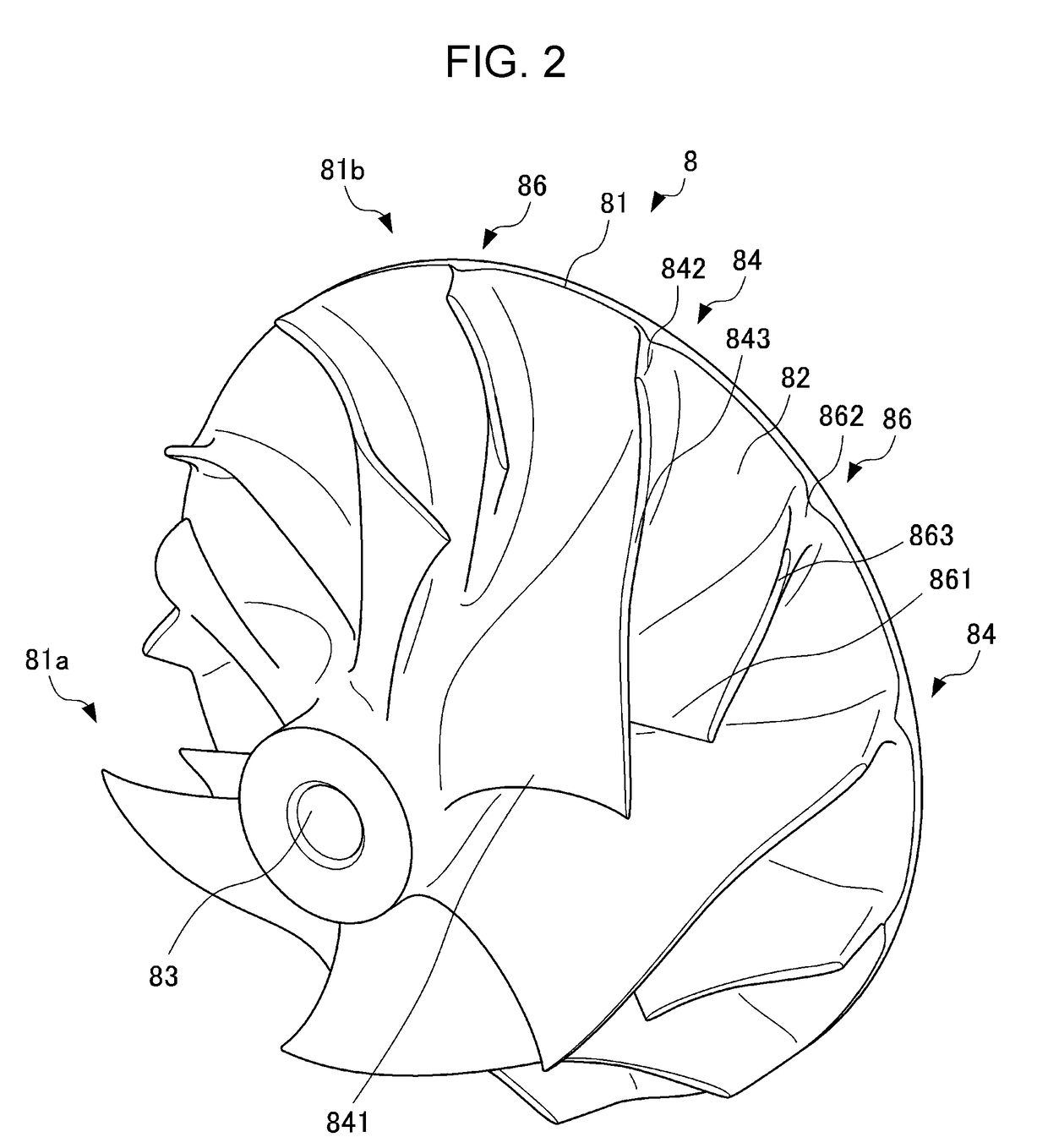
A compressor includes an impeller including blades extending along a shroud. Each of the blades includes a leading edge, a trailing edge, and a tip edge connecting the leading edge and the trailing edge and opposing the shroud. The tip edge has a central curve extending along a center of a thickness of the tip edge from the leading edge to the trailing edge. The central curve has a tangential line touching a contact in the central curve. The tangential line has a tip edge inclination angle made by the rotation axis and the tangential line viewed in a reference direction which passes the contact and which is perpendicular to the rotation axis. The tip edge inclination angle increases as the contact approaches a first maximum inclination point in the central curve. The first maximum inclination point is separated from both the leading edge and the trailing edge.

Description

CROSS-REFERENCES TO RELATED APPLICATIONS[0001]The present application claims priority under 35 U.S.C. §119 to Japanese Patent Application No. 2016-083764, filed Apr. 19, 2016, entitled “Compressor.” The contents of this application are incorporated herein by reference in their entirety.BACKGROUND1. Field[0002]The present disclosure relates to a compressor.2. Description of the Related Art[0003]Hitherto, in a case in which a fixed diffuser is disposed downstream of a compressor that compresses an intake flowing in an intake passage of an internal-combustion engine, the air compressed in the compressor impeller generates a nozzle wake (a pressure fluctuation) when passing through the fixed diffuser. With the above, the compressor impeller positioned upstream receives exciting force caused by the nozzle wake and a phenomenon in which the blades of the compressor impeller vibrate occurs.[0004]Responding to the above, from the viewpoint of securing blade strength against the blade vibrat...

Claims


Application Information

Patent Timeline
IPC IPC(8): F04D29/30F04D29/42F04D29/28F04D29/44F04D17/10
CPCF04D29/30F04D17/10F04D29/441F04D29/4206F04D29/284F04D29/666
Inventor ITOH, NAOKIOANA, MINEYASUKUNO, NAOKI
Owner HONDA MOTOR CO LTD
Learn More