
Drive and control apparatus for multiple-winding motor

Active Publication Date: 2017-10-12
TOSHIBA MITSUBISHI-ELECTRIC IND SYST CORP
View PDF1 Cites 23 Cited by
  • Summary
  • Abstract
  • Description
  • Claims
  • Application Information

AI Technical Summary

Benefits of technology

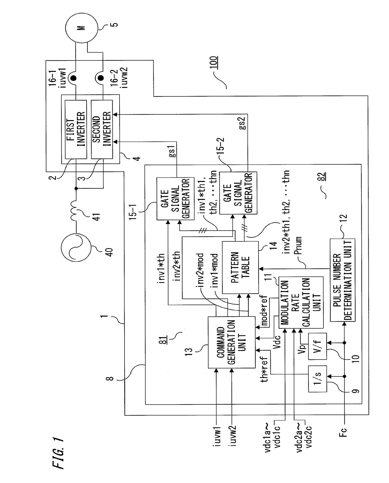
The present invention provides a drive control apparatus for multiple-winding motors that can perform highly accurate correction of imbalance among the voltage phases and amplitudes of multiple inverters while maximizing the use of a small number of times of switching. This is achieved by generating a modulation rate. A pulse number determination unit is used to determine the number of pulses per half cycle of PWM control, and a pattern table is used to generate a switching pattern for reducing a low-order harmonic in output voltage for each number of pulses and modulation rate. The modulation rate phase command generation unit performs control for equalizing currents of power converters, and a phase or frequency at which the control is performed is changed in accordance with the number of pulses. This allows for highly accurate correction of imbalance among the voltage phases and amplitudes of a plurality of inverters, even in the case of using inverters having slow switching speed.

Problems solved by technology

However, this method causes a problem that, for example, if there is imbalance among currents flowing through the respective winding groups, a large-capacity inverter is needed as compared to the balanced case, or if there is imbalance among the current phases, torque ripple occurs among the windings by interference due to magnetic coupling among the windings.

Method used


Image

  • Drive and control apparatus for multiple-winding motor
  • Drive and control apparatus for multiple-winding motor
  • Drive and control apparatus for multiple-winding motor

Examples


embodiment 1

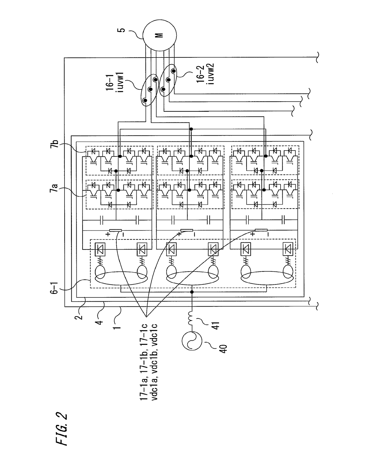
[0031]Embodiment 1 relates to the following drive control apparatus for multiple-winding motor. That is, a control unit includes an output voltage control unit and a PWM control unit. The output voltage control unit includes: an output voltage determination unit; an output voltage phase calculating unit; and a modulation rate phase command generation unit which calculates a modulation rate correction amount and a phase correction amount for equalizing currents flowing through respective windings of a multiple-winding AC motor, on the basis of currents of inverters, and generates a modulation rate command and a phase command for controlling each inverter, on the basis of the calculated correction amounts. The PWM control unit includes; a modulation rate calculation unit; a pulse number determination unit for determining the number of pulses per half cycle of PWM control on the basis of a frequency command; a pattern table for storing switching patterns for reducing low-order harmonic...

embodiment 2

[0106]In drive control apparatus for multiple-winding motor of embodiment 2, a current reference value is set, and currents of inverters are controlled so that the current of each inverter coincides with the current reference value, thereby equalizing currents flowing through respective windings of a multiple-winding AC motor.

[0107]Hereinafter, the configuration and operation of the drive control apparatus for multiple-winding motor in embodiment 2 will be described, focusing on a difference from embodiment 1, with reference to FIG. 10 showing the configuration of a modulation rate phase command generation unit and FIG. 11 showing the configuration of a current equalization controller. In FIGS. 10 and 11, the components that are the same as or correspond to those in FIGS. 3 and 4 are denoted by the same reference characters.

[0108]In the description in embodiment 2, the drawings shown in embodiment 1 will be referred to, as necessary.

[0109]The configuration of the drive control appar...

embodiment 3

[0128]In a drive control apparatus for multiple-winding motor of embodiment 3, one of inverters is used as a reference power converter, and currents of the other inverters are controlled so as to coincide with current of the reference power converter, thereby equalizing currents flowing through respective windings of a multiple-winding AC motor.

[0129]Hereinafter, the configuration and operation of the drive control apparatus for multiple-winding motor in embodiment 3 will be described, focusing on a difference from embodiments 1 and 2, with reference to FIG. 12 and FIG. 13 showing the entire configuration of the drive control apparatus for multiple-winding motor, FIG. 14 and FIG. 17 showing the configuration of a modulation rate phase command generation unit, and FIG. 15, FIG. 16, and FIG. 18 showing the configuration of a current equalization controller. In FIG. 12 to FIG. 18, the components that are the same as or correspond to those in the drawings in embodiments 1 and 2 are deno...


PUM


Abstract

A drive control apparatus for multiple-winding motor includes: a modulation rate phase command generation unit which calculates currents of first and second inverters for driving a multiple-winding three-phase motor and generates a modulation rate command and a phase command for equalizing the currents; a pulse number determination unit which determines the number of pulses per half cycle on the basis of a frequency command; a pattern table for storing switching patterns; and gate signal generators which control the first and second inverters, using an optimal switching pattern based on the number of pulses, wherein the modulation rate phase command generation unit performs control for equalizing currents of the first and second inverters, and the phase or frequency at which the control is performed is changed in accordance with any of the number of pulses, the modulation rate, the frequency command, and the switching pattern.

Description

TECHNICAL FIELD[0001]The present invention relates to a drive control apparatus for multiple-winding motor which drives a multiple-winding motor having a plurality of windings independent of each other in one motor, by a plurality of inverters, and performs variable-speed control for the rotation.BACKGROUND ART[0002]In the case of controlling a multiple-winding motor with their respective winding groups connected in parallel to a plurality of inverters, there is an advantage that it is not necessary to provide a reactor for each inverter in order to prevent cross current, as compared to the case of operating a single-winding motor connected in parallel to a plurality of inverters. In addition, in the case of large capacity, it is possible to combine inverters having unit capacities, in accordance with the load capacity, so that there is an advantage that development and manufacturing of inverters become more effective and thus the cost can be reduced.[0003]However, this method cause...

Claims


Application Information

Patent Timeline
IPC IPC(8): H02P27/08H02P29/50
CPCH02P29/50H02P27/085H02P25/22H02P27/08H02M7/493H02P21/26H02M7/487
Inventor TADA, KEIKOOKAMOTO, YURIKOSATAKE, AKIRASUZUKI, HIROMITSUTSUKAKOSHI, MASAHIKONAKAMURA, RITAKANAKAMURA, MASASHI
Owner TOSHIBA MITSUBISHI-ELECTRIC IND SYST CORP
Learn More