
Security sensing method and apparatus

a technology of security system and sensing method, applied in the field of security systems, can solve the problems of increasing the cost and complexity of installing security system, affecting serviceability, and undesirable wired connections in many security applications, and achieve the effect of facilitating wireless network access to a computer data network

Active Publication Date: 2017-10-12
SENSORMATIC ELECTRONICS CORP
View PDF0 Cites 13 Cited by
  • Summary
  • Abstract
  • Description
  • Claims
  • Application Information

AI Technical Summary

Benefits of technology

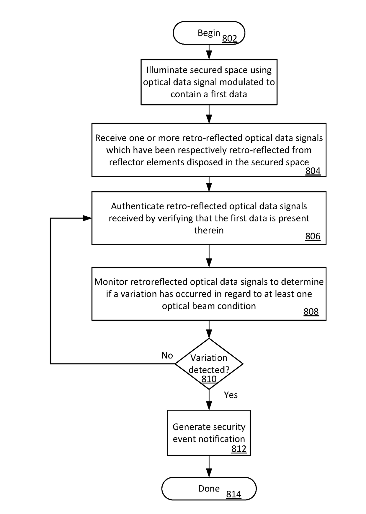
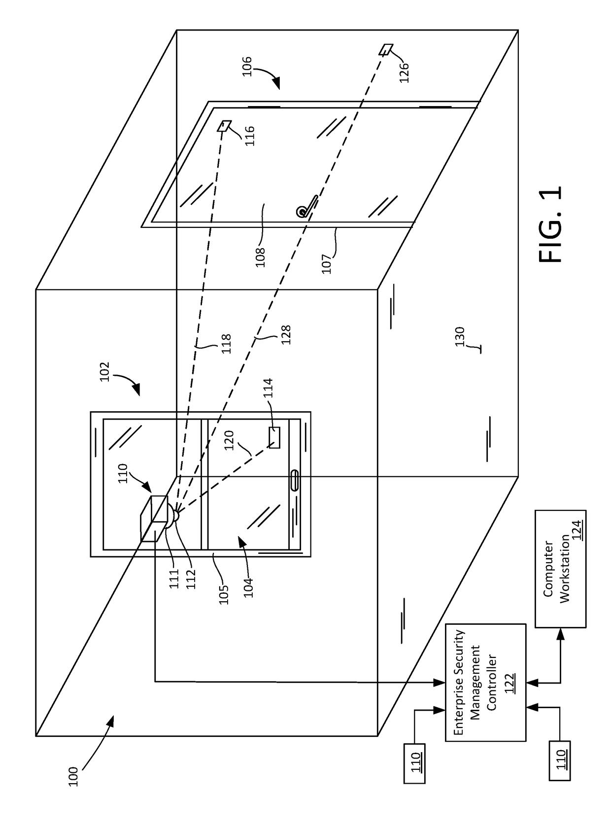
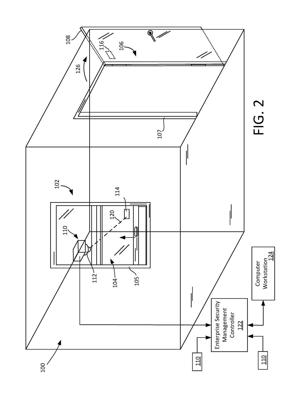
The invention concerns a method and system for performing optical security sensing. It involves using an optical data transceiver to illuminate a secured space with a modulated optical data signal and receive retroreflected optical data signals from reflector elements in the space. The retrieved signals are authenticated by determining the presence of the original data sequence. A security event notification is generated and communicated to an enterprise security management controller if there is a variation in the optical beam condition. The optical data transceiver can also function as a wireless network access point and the optical data signal can comprise at least a portion of a management frame for a wireless communication protocol. The technical effects include improved security sensing, wireless network access, and detection of variations in optical beam conditions.

Problems solved by technology

But the batteries used in such wireless sensors need to be periodically replaced to ensure a properly functioning sensor, thus putting a strain on serviceability.
But it is commonly accepted that wired connections are undesirable in many security applications because the wires provide a point of weakness to the security system.
A further drawback of such conventional wired arrangements is that they tend to increase the cost and complexity of installing the security system.
Such conventional wired or wireless battery powered sensors are susceptible to electrical noise due to environmental disturbances.

Method used


Image

  • Security sensing method and apparatus
  • Security sensing method and apparatus
  • Security sensing method and apparatus

Examples


Embodiment Construction

[0019]It will be readily understood that the components of the embodiments as generally described herein and illustrated in the appended figures could be arranged and designed in a wide variety of different configurations. Thus, the following more detailed description of various embodiments, as represented in the figures, is not intended to limit the scope of the present disclosure, but is merely representative of various embodiments. While the various aspects of the embodiments are presented in drawings, the drawings are not necessarily drawn to scale unless specifically indicated.

[0020]Reference throughout this specification to features, advantages, or similar language does not imply that all of the features and advantages that may be realized with the present invention should be or are in any single embodiment of the invention. Rather, language referring to the features and advantages is understood to mean that a specific feature, advantage, or characteristic described in connect...


PUM


Abstract

Optical data transceiver is used to illuminate a secured space with an optical data signal which has been modulated to contain a first data sequence. One or more retroreflected optical data signals are received at the optical data transceiver from reflector elements disposed in the secured space. The retroreflected optical data signals are authenticated and a security event notification is selectively communicated to an enterprise security management controller if a variation occurs in regard to at least one retroreflected optical beam condition. The variation can involve a disruption of the optical beam and / or a displacement of the optical beam.

Description

CROSS-REFERENCE TO RELATED APPLICATIONS[0001]This application claims the benefit of provisional U.S. Patent Application No. 62 / 319410, filed on Apr. 7, 2016, which is hereby incorporated herein by reference.BACKGROUND OF THE INVENTIONStatement of the Technical Field[0002]The inventive arrangements relate to security systems and more particularly to security systems which employ sensors for detecting the opening and closing of doors and windows.Description of the Related Art[0003]Security systems for homes and commercial establishments commonly employ sensors for detecting the opening and closing of doors and windows. Various types of sensors have been developed for this purpose. For example, some sensors are battery powered and wirelessly coupled to control circuitry associated with a security system or enterprise monitoring system. But the batteries used in such wireless sensors need to be periodically replaced to ensure a properly functioning sensor, thus putting a strain on servi...

Claims


Application Information

Patent Timeline
IPC IPC(8): G08B13/184G08B25/10G08B13/187G08B13/196
CPCG08B13/184G08B13/187G08B25/10G08B13/19626G08B13/08
Inventor PATTERSON, HUBERT A.SEQUEIRA, MELWYN F.
Owner SENSORMATIC ELECTRONICS CORP
Learn More