Ignition control device and ignition control method for internal combustion engine
a control device and ignition control technology, applied in the direction of machines/engines, spark plugs, mechanical equipment, etc., can solve the problems of inability to dielectrically breakdown, leakage of energy supplied to the spark plug, and decrease in the impedance of the other coil pair, so as to prevent engine misfire and low cost
- Summary
- Abstract
- Description
- Claims
- Application Information
AI Technical Summary
Benefits of technology
Problems solved by technology
Method used
Image


Examples
first embodiment
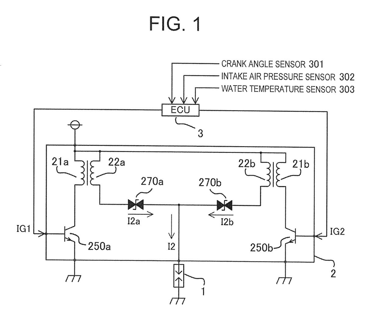
[0028]FIG. 1 is a view showing a configuration of an ignition control device for an internal combustion engine according to a first embodiment of this invention. In FIG. 1, a spark plug 1 connected to an ignition coil 2 is provided in each cylinder of the internal combustion engine. Note that FIG. 1 shows a single extracted cylinder.
[0029]The spark plug 1 includes a first electrode to which an ignition voltage for generating a spark discharge is applied, and a second electrode that opposes the first electrode via a gap and is maintained at a ground potential. Further, when an ignition voltage of the ignition coil 2 is applied between the electrodes, the spark plug 1 generates a spark discharge, thereby igniting a combustible air-fuel mixture existing in a combustion chamber by either forced ignition or self-ignition such that the combustible air-fuel mixture burns. Hereafter, forced ignition and self-ignition will be referred to simply as ignition.
[0030]The ignition coil 2 is mechan...
second embodiment
[0058]FIG. 4 is a view showing a configuration of an ignition control device for an internal combustion engine according to a second embodiment of this invention. In FIG. 4, the ignition coil 2 includes a secondary current detection circuit 280 that detects the discharge secondary current I2a supplied from the secondary coil 22a. All other configurations are identical to the first embodiment, shown in FIG. 1, and therefore description thereof has been omitted.
[0059]The secondary current detection circuit 280 inputs a detected secondary current output Vi2 into the ECU 3, and the ECU 3 re-energizes the primary current supplied to the primary coil 21b on the basis of the value of the secondary current output Vi2. Further, one end of the secondary current detection circuit 280 is connected to the secondary coil 22a, and the other end is grounded.
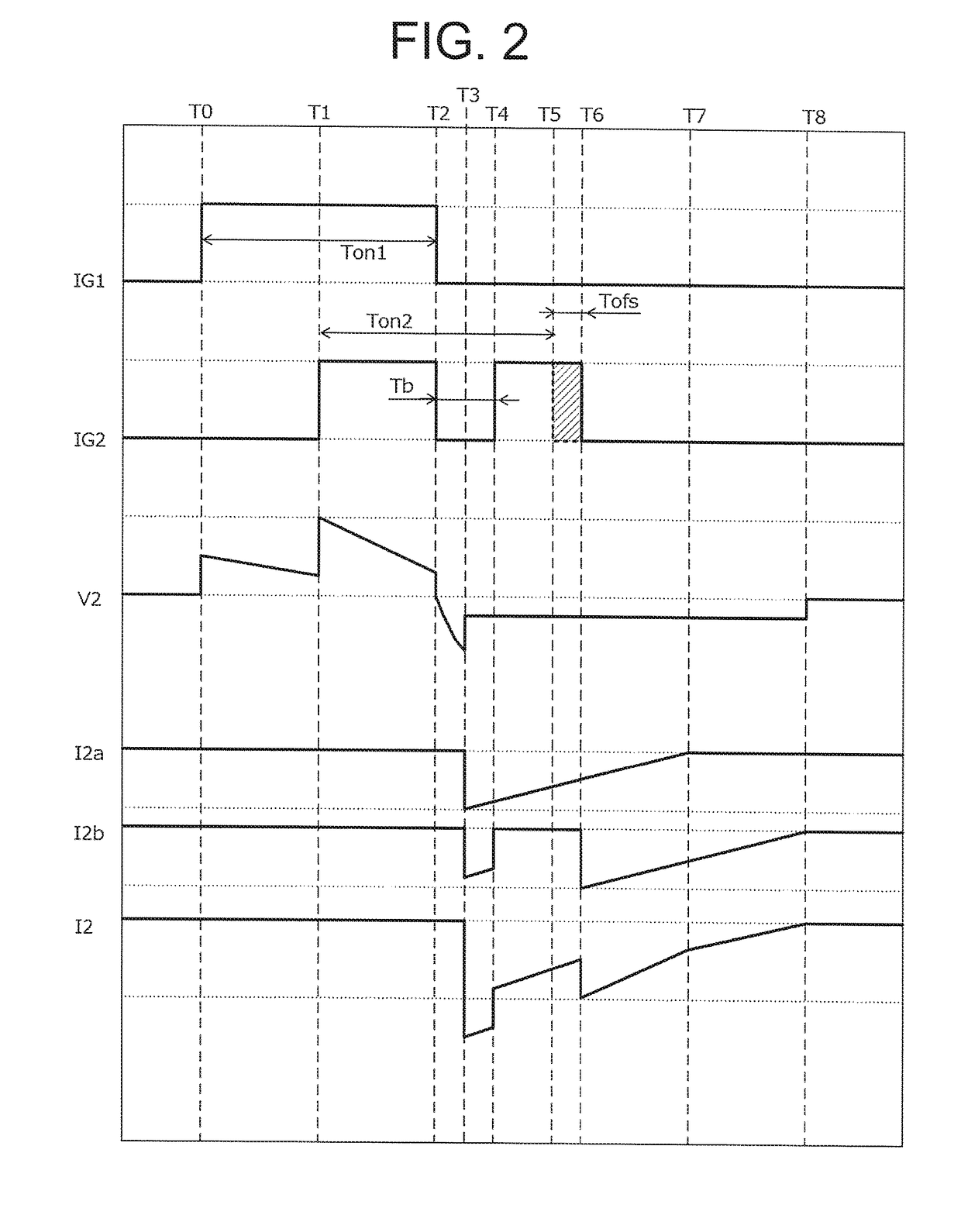
[0060]Next, referring to FIG. 2, a specific operation of the ignition control device for an internal combustion engine having the above configu...
third embodiment
[0064]FIG. 5 is a view showing a configuration of an ignition control device for an internal combustion engine according to a third embodiment of this invention. In FIG. 5, the ignition coil 2 includes an ion current detection circuit 240 provided in relation to the secondary coil 22b. All other configurations are identical to the first embodiment, shown in FIG. 1, and therefore description thereof has been omitted.
[0065]The ion current detection circuit 240 applies a bias voltage of approximately several hundred V between the first electrode and the second electrode of the spark plug 1, and detects an ion current that flows on the basis of an amount of ions generated when the combustible air-fuel mixture in the combustion chamber is burned, and a leak current generated when an insulation resistance value between the first electrode and the second electrode of the spark plug 1 decreases such that the spark plug smolders. Note that when the spark plug smolders, a leak path 12 indicat...
PUM
 Abstract
Description
Claims
Application Information
 - R&D
- Intellectual Property
- Life Sciences
- Materials
- Tech Scout
- Unparalleled Data Quality
- Higher Quality Content
- 60% Fewer Hallucinations
Browse by: Latest US Patents, China's latest patents, Technical Efficacy Thesaurus, Application Domain, Technology Topic, Popular Technical Reports.
© 2025 PatSnap. All rights reserved.Legal|Privacy policy|Modern Slavery Act Transparency Statement|Sitemap|About US| Contact US: help@patsnap.com