Bearing structure of turbocharger

Inactive Publication Date: 2017-10-12
OTICS CORP
View PDF0 Cites 6 Cited by
  • Summary
  • Abstract
  • Description
  • Claims
  • Application Information

AI Technical Summary

Benefits of technology

The patent describes a bearing structure for a turbocharger that reduces noise, improves efficiency, and lowers manufacturing costs. The structure includes an oil film damper between the inner ring of an angular ball bearing and the rotor shaft. This arrangement eliminates the need for a large inertial mass inside the oil film damper and reduces the contact area between the damper and the rotor shaft, resulting in reduced viscous force. Additionally, the inner diameter of the angular ball bearing is smaller than the outer diameter of the outer ring, further reducing viscous force.

Problems solved by technology

As a result, viscous force between the oil film damper and the outer ring tends to be large and, especially under low temperature environment, viscosity increases significantly.
When the (inertial) mass of the components inside the oil film damper is large and the viscous force is high, however, the eccentric rotation of the rotation body assembly is hindered and thus the rotation body assembly has to rotate about a position close to the centroid.
As a result, unusual noise may be generated during initial rotation or the impellers may contact the housing and be damaged.
These problems are more serious under low temperature environment.
The increased tip clearance, however, causes a decrease in operation efficiency of a turbocharger.
In this configuration, however, the mass balance needs to be adjusted with high accuracy, which results in cost increase.
If screw hole machining is performed on the rotor shaft for co-rotation of the components inside the oil film damper and the components outside the oil film damper, adjustment of the mass balance of the rotation body assembly needs more time and effort, which results in cost increase.
Further, if screw hole machining is performed on the rotor shaft, a screw hole concentratedly suffers stress, which may cause a decrease in fatigue strength of the rotor shaft.
However, the large diameter of the rotor shaft needs to increase the size of a ball bearing.
Thus, the contact area of the oil film damper and the ball bearing increases and the viscous force between the oil film damper and the ball bearing also increases, which decreases the operation efficiency of the turbocharger.
Moreover, there is a problem that a high-speed rotation of the rotor shaft easily unfastens a screw directly fastened to the rotor shaft.

Method used


Image

  • Bearing structure of turbocharger
  • Bearing structure of turbocharger
  • Bearing structure of turbocharger

Examples


embodiment 1

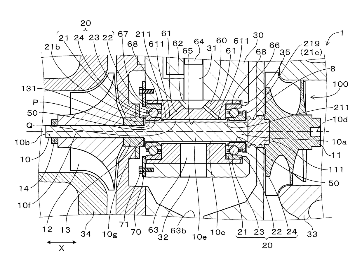
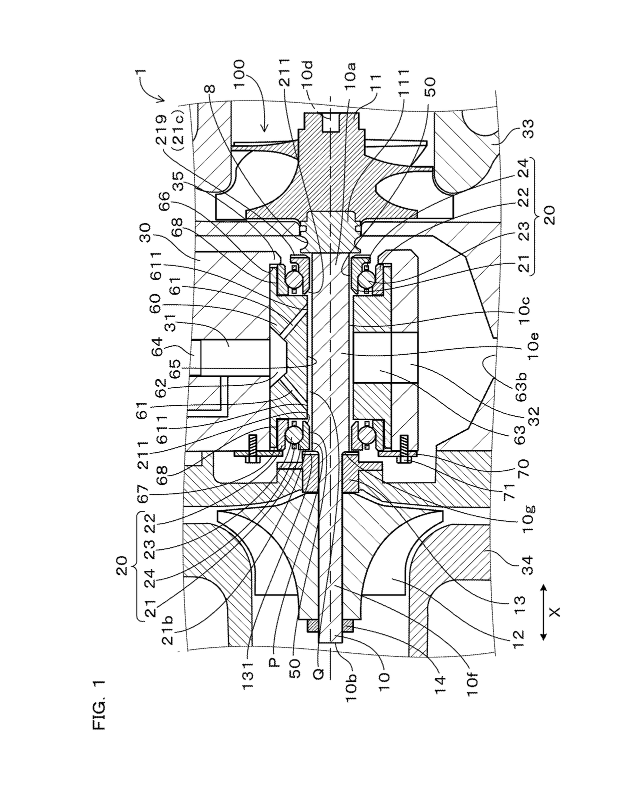
[0026]A bearing structure of a turbocharger 1 according to an embodiment is described with reference to FIGS. 1 to 4.

[0027]As shown in FIG. 1, the bearing structure 1 according to the present embodiment includes a rotor shaft 10, an angular ball bearing 20, a retainer 60, and a housing 30.

[0028]A turbine impeller 11 is mounted on a first end 10a of the rotor shaft 10 and a compressor impeller 12 is mounted on a second end 10b thereof.

[0029]Two angular ball bearings 20 are provided and each of the angular ball bearings 20 includes an inner ring 21 and an outer ring 22 that are supported in relatively rotatable manner. The rotor shaft 10 is inserted into the inner ring 21.

[0030]The retainer 60 holds the outer ring 22.

[0031]The housing 30 houses therein the rotor shaft 10, the angular ball bearings 20, and the retainer 60 to constitute a bearing housing.

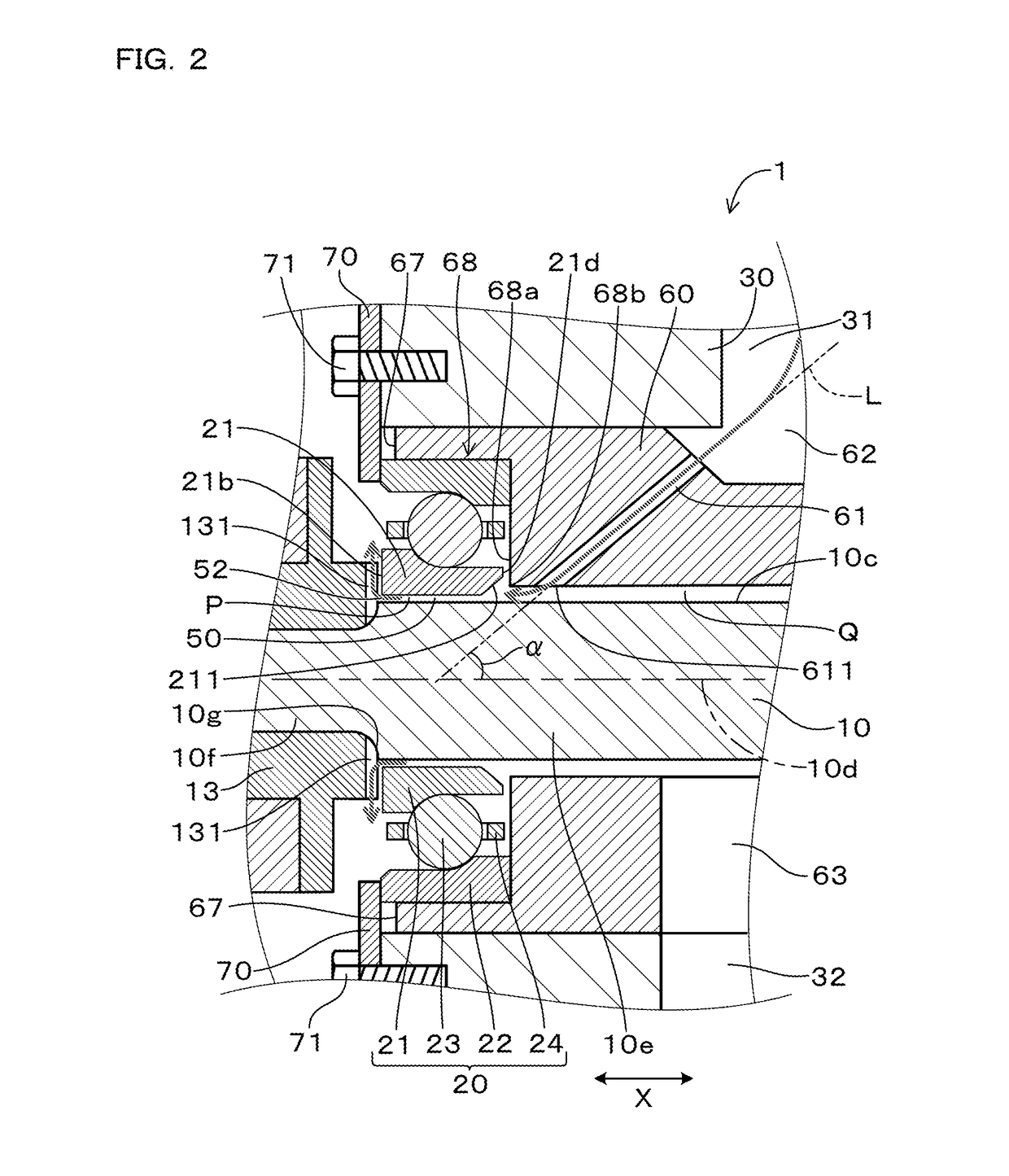
[0032]An oil film damper 50 is formed of oil in a film state and is interposed between the inner ring 21 and an outer peripheral surfa...


PUM


Abstract

A bearing structure of a turbocharger includes a rotor shaft, two angular ball bearings, a retainer, a housing, and an oil film damper. Each of the angular ball bearings includes an inner ring and an outer ring that are supported in relatively rotatable manner. The rotor shaft is inserted into the inner ring. The retainer holds the outer ring. The housing houses therein the rotor shaft, the angular ball bearings, and the retainer to constitute a bearing housing. The oil film damper is formed of oil in a film state and is interposed between the inner ring and an outer peripheral surface of the rotor shaft. The inner ring is configured to rotate with rotation of the rotor shaft via the oil film damper.

Description

CROSS-REFERENCE TO RELATED APPLICATION[0001]The present application claims priority under 35 U.S.C. §119 to Japanese Application No. 2016-076652, filed on Apr. 6, 2016, entitled “BEARING STRUCTURE OF TURBOCHARGER”. The contents of this application are incorporated herein by reference in their entirety.BACKGROUND OF THE INVENTIONField of the Invention[0002]The present invention relates to a bearing structure of a turbocharger.Description of the Related Art[0003]An internal combustion engine has been conventionally provided with a turbocharger which utilizes a flow of exhaust gas discharged from the internal combustion engine to compress intake air. The turbocharger includes a rotor shaft, a turbine impeller provided at one end of the rotor shaft, and a compressor impeller provided at the other end of the rotor shaft, and the rotor shaft is borne by a bearing structure. The bearing structure is housed in a bearing housing. JP-A-2012-92934 discloses a turbocharger that includes, as suc...

Claims


Application Information

Patent Timeline
IPC IPC(8): F01D25/16F16C27/04F04D29/059F04D29/28F04D29/053F16C19/54F01D5/04
CPCF01D25/164F16C19/548F16C27/045F01D5/04F04D29/284F05D2240/54F04D29/059F16C2360/24F05D2220/40F05D2240/60F04D29/053F01D25/16F01D25/162F05D2260/96F01D25/18F16C33/6659F16C33/6685F16C35/077F16F15/0237F16C19/163
Inventor ISOGAI, TOMOYUKI
Owner OTICS CORP
Why Eureka
Try Eureka