Dmd projector with tir prism

Active Publication Date: 2017-10-05
BAE SYSTEMS PLC
View PDF9 Cites 7 Cited by
  • Summary
  • Abstract
  • Description
  • Claims
  • Application Information

AI Technical Summary

Benefits of technology

The patent describes a method to reduce optical distortions in a prism assembly used for projecting light. The method involves using a panel to reflect light into the prism in a way that minimizes the angle at which the light travels through the prism. This reduces optical distortions and ensures that light is output from the prism in a way that is clear and accurate. The technical effect of this method is to improve the performance of prism assemblies used in lighting and display applications.

Problems solved by technology

The drawback with this is the required increase in build cost and complexity, especially since these prisms are bespoke optical elements.
Another drawback occurs when multi-element prism assemblies are employed in an attempt to suitably direct light.
In particular, this is the introduction of multiple air-gaps in the path downstream of the DMD, which degrade the projected image resolution.

Method used


Image

  • Dmd projector with tir prism
  • Dmd projector with tir prism
  • Dmd projector with tir prism

Examples


Embodiment Construction

[0038]In the drawings, like items are assigned like reference symbols.

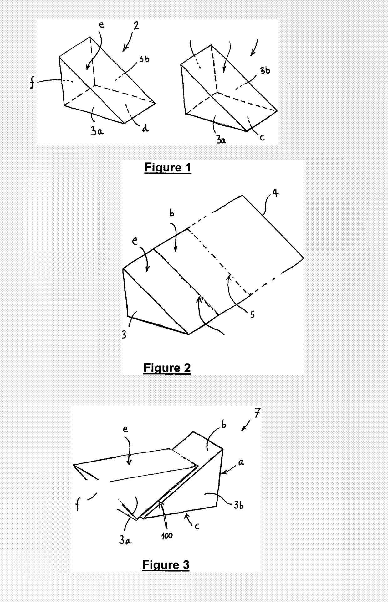
[0039]FIG. 1 illustrates two substantially identical triangular prism pieces (1, 2). Each prism piece is a triangular prism having three non-base surfaces (a, b, c; d, e, f) extending between a respective parallel pair of triangular, substantially congruent “base” surfaces (3a, 3b). Each prism piece has the following three internal angles of 97.2°, 49.5° and 33.3°. In each prism piece, a smallest of the three non-base surfaces (a, f) joins the largest non-base surface (b, e) at an internal angle of 49.5°, and joins the remaining (second-largest) non-base surface (c, d) at an internal angles of 97.2°. Thus, in each prism, the largest and second largest non-base surfaces meet at an internal angle of 33.3°. It will be appreciated that these angles will change if the refractive index of the material of the prism is changed.

[0040]In this example, each prism piece is made from the common Schott borosilicate glass N-BK7,...


PUM


Abstract

A projection apparatus comprising a prism assembly 7 including an input sub-prism 1 possessing a first interface surface and an output sub-prism 2 adjacent to the input sub-prism possessing a second interface surface. The second interface surface is spaced from the first interface surface immediately proximate to it and extends over it to receive display light 12 transmitted through the first interface surface. A panel 8 comprising a plurality of selectively adjustable reflecting elements is arranged to receive from the input sub-prism an illumination light totally internally reflected from the first interface surface and selectively to reflect received illumination light back through the input sub-prism for transmission through the first interface surface for receipt as display light 13 by the output prism at said second interface surface.

Description

FIELD OF THE INVENTION[0001]The invention relates to displays such as, but not limited to, projection displays for projecting display light.BACKGROUND[0002]The total internal reflection (TIR) if illumination light within a prism is a known method of directing illumination light on to a DMD (digital micro-mirror device) for use in reflecting that light as a projectable display. By selectively separating the light reflected from DMD pixels, one may control what light is projected, and when. A prism may be used in this way to exploit total internal reflection (TIR) to direct “selected” light and “deselected” light through different exit faces of the prism. This allows the projector system to keep “de-selected” light out of a subsequent projector lens.[0003]The drawback with this is the required increase in build cost and complexity, especially since these prisms are bespoke optical elements. Another drawback occurs when multi-element prism assemblies are employed in an attempt to suita...

Claims


Application Information

Patent Timeline
IPC IPC(8): G03B21/28G02B5/04G02B27/01G03B21/00
CPCG03B21/28G02B27/0101G02B5/04G03B21/008G03B21/2066H04N9/3102
Inventor MORANT, PAUL STEWARTHOGG, GRAHAM LAURENCE
Owner BAE SYSTEMS PLC
Why Eureka
Try Eureka