Light guide, especially for signal lamps of motor vehicles

a technology for signal lamps and light guides, which is applied in vehicle lighting systems, lighting and heating apparatuses, instruments, etc., can solve the problems of reducing the efficiency of the output characteristic required by regulations, and affecting the efficiency of the output characteristi

Active Publication Date: 2017-10-05
PO LIGHTING CZECH SRO
View PDF2 Cites 3 Cited by
  • Summary
  • Abstract
  • Description
  • Claims
  • Application Information

AI Technical Summary

Benefits of technology

The invention is a light guide for signal lamps in motor vehicles. It includes a collimator and a light guiding body. The light guiding body is elongated and has at least one transitional surface that emits light. It is designed to emit light within a certain angle of diffusion from the optical axis. The light guide is made of a material with a specific refractive index and emits light rays mainly within a range of 5° to 25°. It can be designed for a single reflection of a particular light ray from the transitional surface. The light guide can also have a superstructural segment that is constant in height and positioned between the collimator and the transitional surface. The profile of the light guide is symmetrical with respect to the longitudinal axis. It can have at least two transitional surfaces that differ in the length and / or height of their inclination. The technical effects of the invention are improved light beam control and optimized lighting performance.

Problems solved by technology

Light guides of thin dimensions do not completely bind light into the light guide and a part of the light rays is lost.
However, if a collimator with bigger dimensions is used at the input, a thin light emitting output surface cannot be easily provided at the output unless the light guide gets narrower in the direction from the light source.
But if the light rays are reflected in various ways inside the light guide body, they may exit under any angle from the output surface, which reduces efficiency with respect to the output characteristic required by regulations.
However, variability of the mechanical design of the light device is very often limited, which affects the emission characteristics of the resulting light trace or requires adaptation of the mechanical design of the light device or even redesigning of the entire light guide.

Method used


Image

  • Light guide, especially for signal lamps of motor vehicles
  • Light guide, especially for signal lamps of motor vehicles
  • Light guide, especially for signal lamps of motor vehicles

Examples


first embodiment

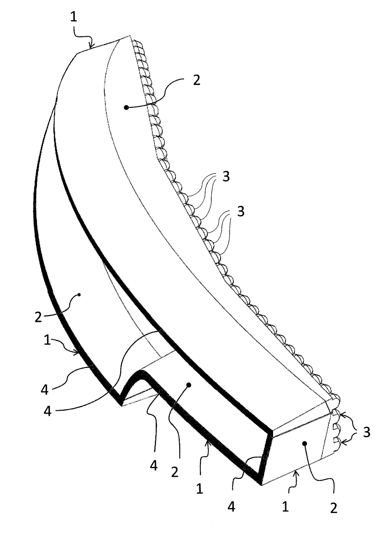
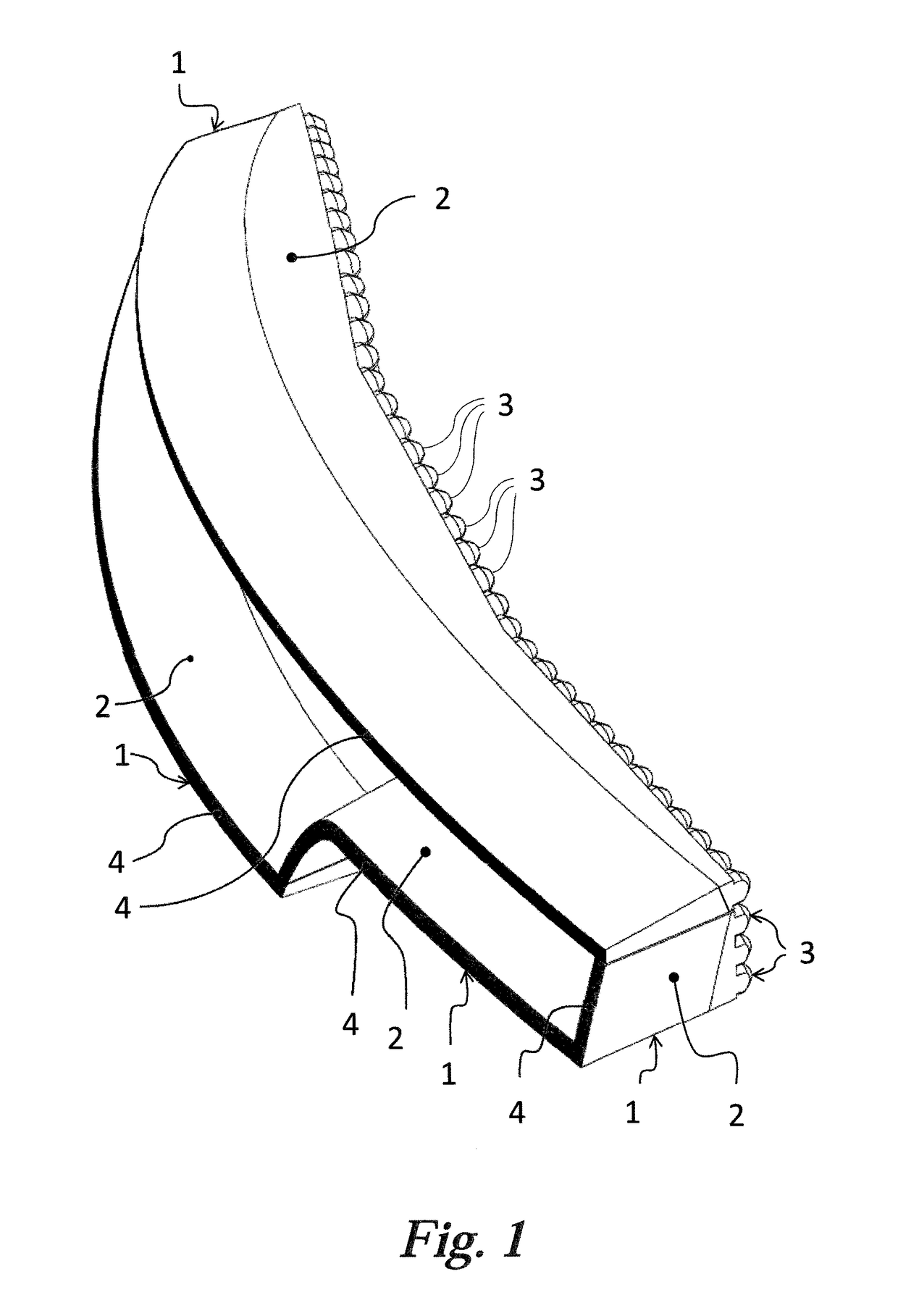
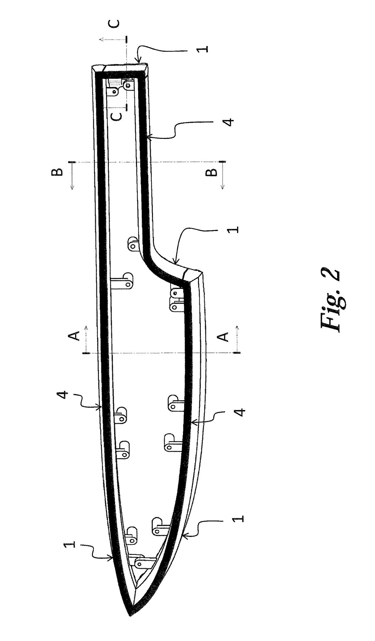
[0022]FIGS. 1, 2, 3 and 4 show the light guides in accordance with the invention in different views. The light device comprises four light guides implemented in the form of integral, spatially shaped planar elements 1. Each light guiding element 1 comprises a planarly shaped light guiding body 2 adapted to conduct light. The light guiding body 2 is designed as light conducting, and is fitted with collimators 3 at its entry part and with a continuous emitting surface 4 on its outer side. In addition, the light guiding body 2 gets narrower from the collimator 3 towards the emitting surface 4, i.e. the longitudinal profile gets smaller in the direction of the optical axis x. Each emitting surface 4 of the light device is adapted to provide a different light function, e.g. to emit the positional, brake, direction indicator or fog light, the emitting surfaces 4 creating a certain designer element.

[0023]FIG. 5 represents a detailed view of the first embodiment of the light guide, which is...

second embodiment

[0029]FIG. 6 shows the light guide, which comprises two transitional surfaces 22 with different inclination lengths b, b′ and different inclination heights a, a′. Either transitional surface 22 is subject to the above mentioned relationship between the inclination length b of this transitional plane 22 and the inclination height a of this inclination plane 22. The collimator 3 is designed as symmetrical, while between the collimator 3 and the shorter inclination length b′ a superstructural element 23 is situated.

third embodiment

[0030]FIG. 7 shows the light guide wherein the light guiding body 2 contains a superstructural segment 23 having the length e, which is situated between the collimator 3 and the transitional surfaces 22, its longitudinal profile being constant in the direction from the collimator 3 to the transitional surfaces 22 of the body 2. End light ray 101 generally delimits, in vertical direction, a boundary of an angle range within which rays 100 are emitted from the emitting surface 4. In another embodiment, the superstructural element may be beveled under a withdrawing angle to improve moldability, depending on the mold design, in the direction towards or from the collimator.


PUM


Abstract

The light guide, especially for motor vehicle signal lamps, comprises a collimator with a collimating wall for binding and routing light rays, and a light guiding body that continues the collimating wall, is of a material with refractive index (n), and is integral, spatially shaped, planar, and fitted at its end with an output emitting surface providing a signal light function. The first height (d) of the body at its beginning where it adjoins the collimating wall, is bigger than its second height where it passes into the emitting surface. The body is adapted to emit light rays generally within angle (ω) of diffusion from the optical axis (x), and comprises a transitional surface that is, in its profile towards the emitting surface, inclined towards the longitudinal axis of the profile. The ratio of inclination height (a) and inclination length (b) of the transitional surface is defined as:ab=tg(12arcsin(sinωn))

Description

FIELD OF THE INVENTION[0001]The invention relates to a light guide, especially for signal lamps of motor vehicles, thus belonging to the field of the design of optical devices intended mainly for indication of a vehicle or signaling for other traffic participants. The light guide is especially designed to achieve the required emission characteristic of the output light trace of a signal lamp of motor vehicles.BACKGROUND INFORMATION[0002]In the field of the lighting equipment design of motor vehicles, a special position is occupied by light guides whose elongated shape makes them suitable to create light lines, e.g. to emit a position, brake, fog, indicator or day light. At present, light guides often fulfill signal light functions subject to higher requirements for the luminous flux, as e.g. the daily light in headlights and the rear brake and direction indication lights in the rear lamps. Semiconductor LEDs (light emitting diodes) are most frequently used to generate light, being p...

Claims


Application Information

Patent Timeline
IPC IPC(8): F21S8/10
CPCF21S48/2262F21S48/225G02B6/42G02B6/26F21S43/14F21S43/27F21S43/241F21S43/243F21S43/249G02B6/0021G02B6/0045G02B6/0001
Inventor GLOSS, TOMASMATEJU, TOMASHRUSKA, JAKUB
Owner PO LIGHTING CZECH SRO
Why Eureka
Try Eureka