Method for 3D printing of buildings and a device for implementation thereof

a 3d printing and building technology, applied in the field of construction, can solve the problems of insufficient strength of building structures, shortcoming of prior art analogs, low efficiency, etc., and achieve the effects of ensuring wear resistance and decorative function, reducing labor intensity, and reducing labor intensity

Inactive Publication Date: 2017-10-05
KULMAGAMBETOV ANUAR RAYKHANOVICH
View PDF10 Cites 7 Cited by
  • Summary
  • Abstract
  • Description
  • Claims
  • Application Information

AI Technical Summary

Benefits of technology

The present invention expands the range of printing buildings to include multi-story buildings that require stronger and reinforced walls to withstand greater loads. The invention also allows for the printing of walls using various materials to create coatings with additional functions, such as wear resistance and decorative appearance.

Problems solved by technology

The shortcomings of the prior art analog consist in low efficiency, since building components are first cast into molds and subsequently the individual components are assembled into a building.
The shortcomings of the prior art prototype of the method and the prototype of the device consist in insufficient strength of the building structures manufactured by this method utilizing this device, since materials with poor mechanical properties are used for printing, thereby preventing the possibility of printing multi-story buildings.

Method used


Image

  • Method for 3D printing of buildings and a device for implementation thereof
  • Method for 3D printing of buildings and a device for implementation thereof
  • Method for 3D printing of buildings and a device for implementation thereof

Examples


first embodiment

[0020]One example of a specific implementation of the method for 3D printing of buildings using the present invention will be now more particularly described.

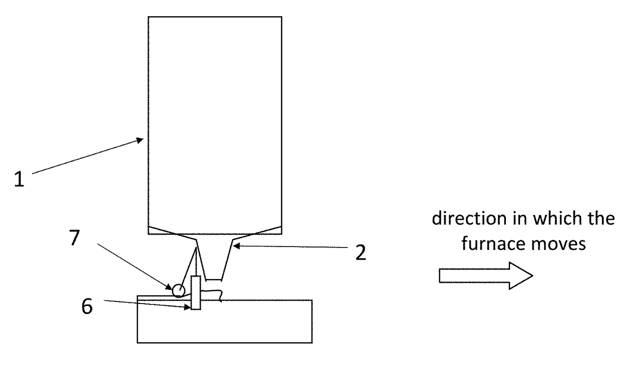
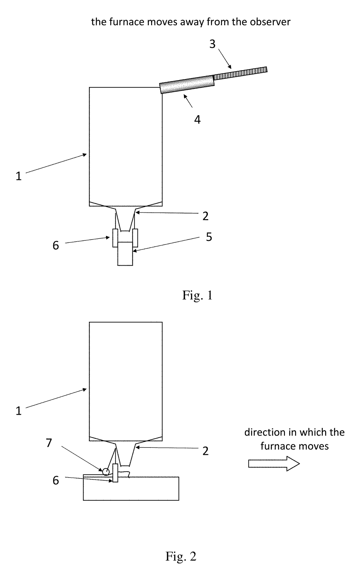
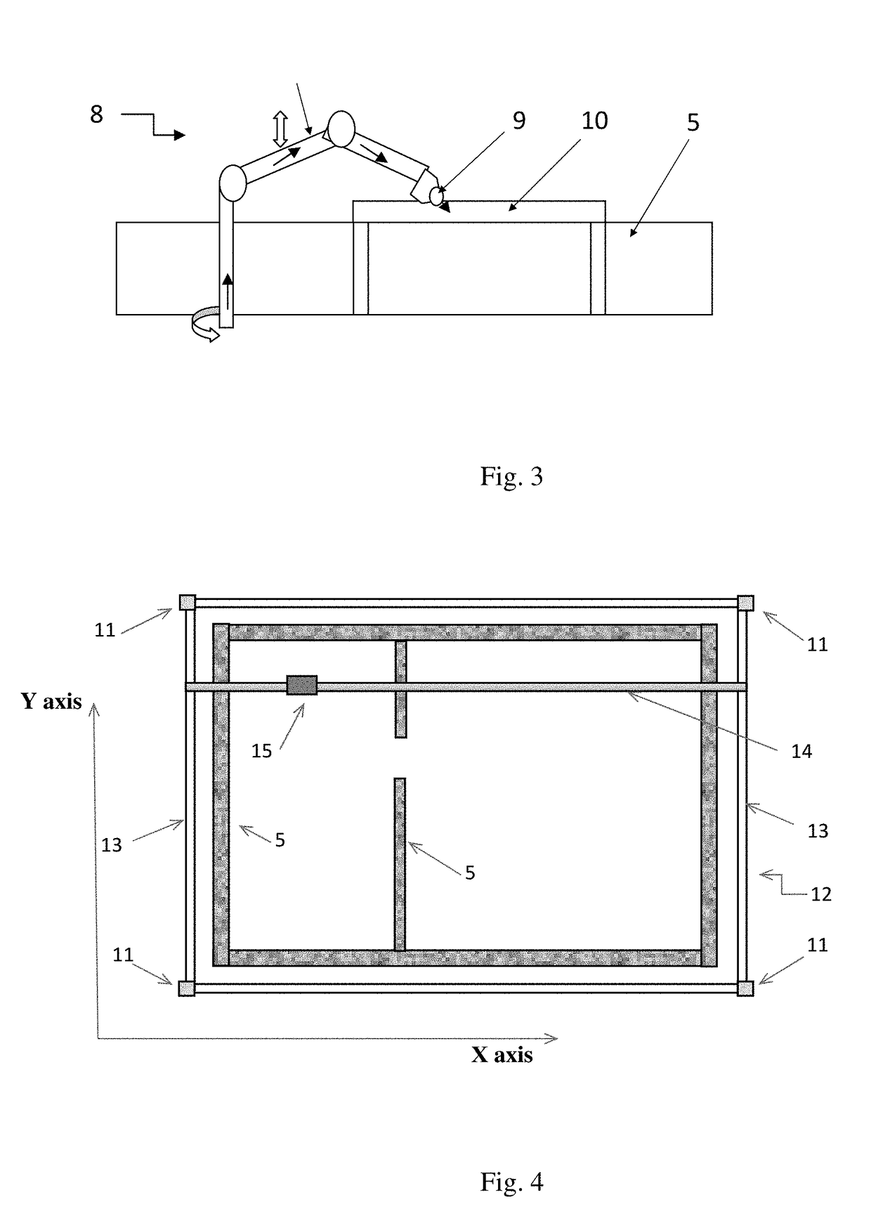
[0021]Three print heads are used in said example of specific implementation. Mobile glass melting furnaces 1 are the said print heads, wherein one of said furnaces is shown in FIGS. 1 and 2. The furnaces are used to melt raw material and feed the melt in a dosed manner to the planned sites of construction of building structures such as walls. Therefore, the furnaces are moved in 3D space using a 3D positioning mechanism along the trajectories corresponding to the arrangement of walls 5 of the building under control of a computer program, same as in a 3D printer. Thereupon, the process of fabrication of structures for buildings is referred to as printing. In terms of physics, the process of feeding melt is known as casting; therefore, we will subsequently use the term “casting” to describe feeding of the melt.

[0022]The density o...

second embodiment

[0028]For the present method, the technical result is accomplished due to alignment of the non-hardened material in the building structure and due to the installation of some additional structural elements that cannot be printed when casting the entire structure of the building. Aligning the material before it melts ensures accuracy in dimensions of the building structure, thereby enhancing strength and stability of the building. The alignment procedure is unavoidable when printing structures of the buildings made of melted silicates. Such materials are characterized by high strength required for 3D printing of multi-story buildings, while simultaneously having high melting point and low hardening rate, which makes alignment of a printed structure necessary. Installation of additional elements is needed during 3D printing of multi-story buildings. Such elements as beams for window and door openings made of steel or reinforced concrete allow one to considerably enhance floor strength...


PUM

PropertyMeasurementUnit
densityaaaaaaaaaa
densityaaaaaaaaaa
densityaaaaaaaaaa

Abstract

3D printing of buildings consisting in deposition of the material of walls by a print head as the print head is moved along the 3D coordinates of future walls is achieved by simultaneous utilization of several print heads, simultaneous loading the material into the print heads, melting the material in print heads, dosed feeding of the melted material through an opening in the print heads as the heads are moved along the 3D coordinates, as the building is constructed.

Description

CROSS-REFERENCE TO RELATED APPLICATION[0001]The instant application claims priority to Russian Patent Application Serial No. 2016112588 filed Apr. 4, 2016, the entire specification of which is expressly incorporated herein by reference.FIELD OF THE INVENTION[0002]The invention relates generally to the field of construction, and in particular, to the method for constructing buildings.BACKGROUND OF THE INVENTION[0003]The prior art analog disclosed in the RF patent No. 2,371,557 with the priority dated Oct. 27, 2009 describes the method for construction of buildings wherein wall panels, partitions and floors are manufactured and then mounted using electric hoists of the overhead gantry crane; wall panels, partitions and floors are fabricated by melting of rocks and using this mixture to cast metal and rock pieces.[0004]The shortcomings of the prior art analog consist in low efficiency, since building components are first cast into molds and subsequently the individual components are as...

Claims


Application Information

Patent Timeline
Patent Type & Authority Applications(United States)
IPC IPC(8): C03B19/02B33Y30/00B33Y10/00
CPCC03B19/02B33Y30/00B33Y10/00E04G21/00E04G21/0436E04G21/0463C03B17/00E04G21/16
Inventor KULMAGAMBETOV, ANUAR RAYKHANOVICH
Owner KULMAGAMBETOV ANUAR RAYKHANOVICH
Why Eureka
Try Eureka