S-Shaped Coupling Spring for Middle Ear Implants

a technology of middle ear implants and coupling springs, which is applied in the field of medical implants, can solve problems such as non-reproducible results

Active Publication Date: 2017-10-05
MED EL ELEKTROMEDIZINISCHE GERAETE GMBH
View PDF0 Cites 0 Cited by
  • Summary
  • Abstract
  • Description
  • Claims
  • Application Information

AI Technical Summary

Benefits of technology

The present invention relates to a middle ear implant arrangement with an electromechanical transducer that can stimulate the cochlea of a recipient patient. A loading spring is used to connect the transducer to a fixed anatomical structure within the middle ear. The loading spring has a specific shape and is designed to create a loading force within a specific range. The exact value of the force depends on the distance between the transducer and the fixed anatomical structure on the back end. The technical effect of this invention is that it provides a safer and effective way to stimulate the cochlea of a recipient patient through a middle ear implant arrangement with an electromechanical transducer.

Problems solved by technology

But this approach depends very much on the exact execution of the filling of the fascia piece 205, which is manually cut to size by the surgeon and yields non-reproducible results.

Method used


Image

  • S-Shaped Coupling Spring for Middle Ear Implants
  • S-Shaped Coupling Spring for Middle Ear Implants
  • S-Shaped Coupling Spring for Middle Ear Implants

Examples


Embodiment Construction

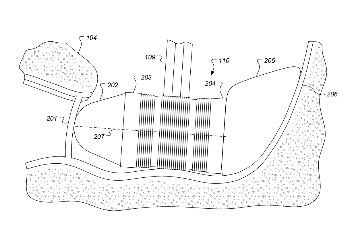
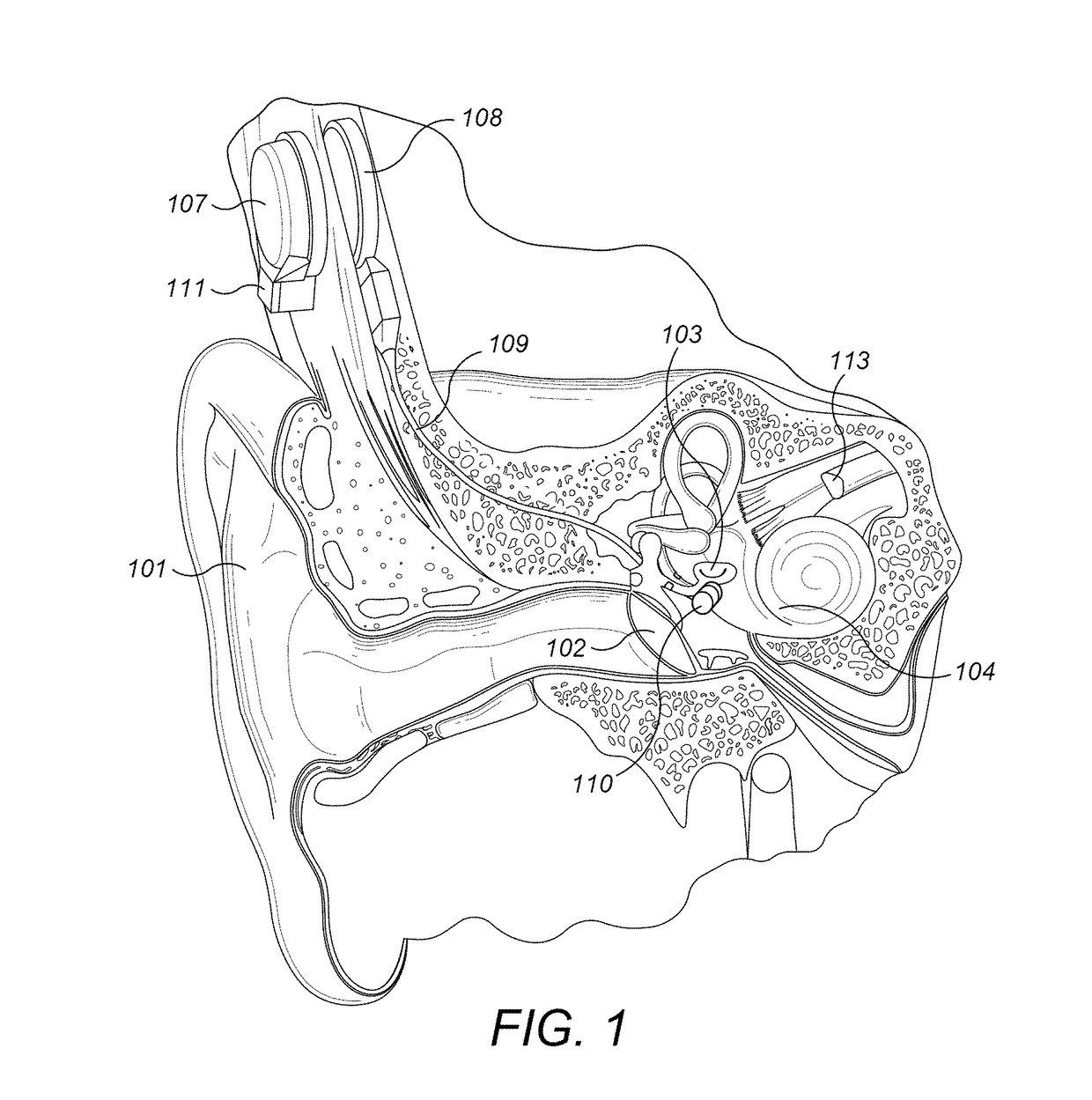
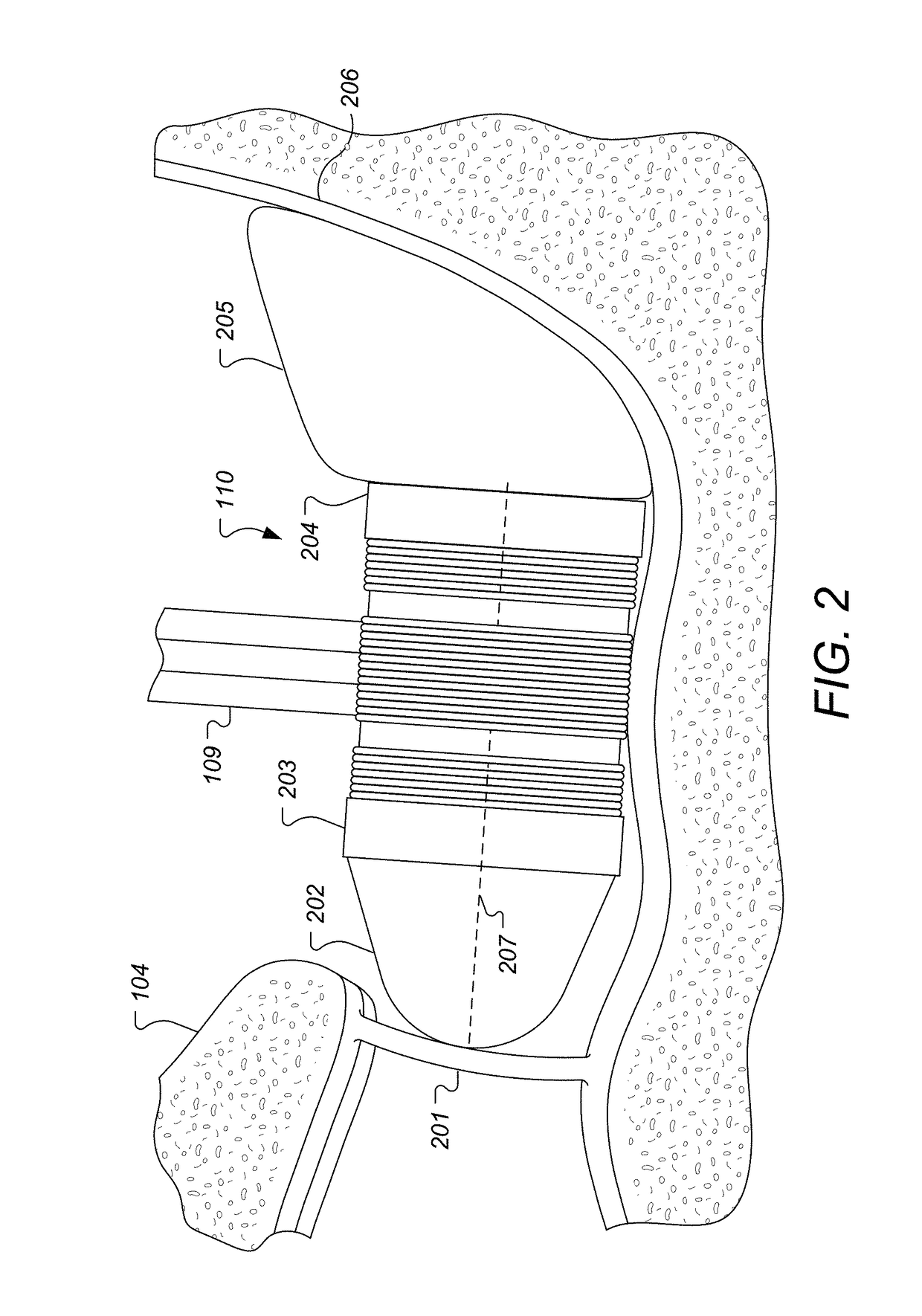
[0015]Various embodiments of the present invention are directed to a middle ear implant arrangement based on an improved loading spring for a middle ear transducer. The spring is adapted to develop a loading force that presses against one end of the electromechanical transducer to firmly engage it against an outer surface of the patient's cochlea (e.g. the round window) with a force that is within a defined range and entirely along the center axis of the transducer, which is also a central axis of the loading spring. For example, the middle ear transducer may be an FMT 110 as shown in FIGS. 1 and 2 with an inner end 203 and an outer end 204. The ends are connected by a center axis 207, and with a conical cochlear engagement member 202 at the inner end 203 with a cochlear engagement surface that couples the mechanical stimulation signal to the round window membrane 201 in the outer cochlear surface.

[0016]FIG. 4 shows one specific embodiment where a loading spring has an inner end 400...


PUM


Abstract

A loading spring has an inner end that engages the outer end of a middle ear transducer, an outer end that engages a fixed anatomical structure within the middle ear of the recipient patient, and a center of mass located on a common line between the inner end and the outer end. The loading spring also has an s-shape with a central spring axis along the common line. And the loading spring is configured for displacement of the inner end and the outer end along the central spring axis to fit the loading spring between the transducer and the fixed anatomical structure with a loading force that is within a defined range and entirely along a center axis of the middle ear transducer and the central spring axis.

Description

[0001]This application claims priority from U.S. Provisional Patent Application 62 / 314,429, filed Mar. 29, 2016, which is incorporated herein by reference in its entirety.TECHNICAL FIELD[0002]The present invention relates to medical implants, more specifically to a novel coupling device for a middle ear prosthesis system.BACKGROUND ART[0003]A normal ear transmits sounds as shown in FIG. 1 through the outer ear 101 to the tympanic membrane (eardrum) 102, which moves the ossicles of the middle ear 103 (malleus, incus, and stapes) that vibrate the oval window and round window openings of the cochlea 104. The cochlea 104 is a long narrow organ wound spirally about its axis for approximately two and a half turns. It includes an upper channel known as the scala vestibuli and a lower channel known as the scala tympani, which are connected by the cochlear duct. The cochlea 104 forms an upright spiraling cone with a center called the modiolar where the spiral ganglion cells of the acoustic n...

Claims


Application Information

Patent Timeline
Patent Type & Authority Applications(United States)
IPC IPC(8): A61N1/36H04R25/00
CPCH04R25/606A61N1/36032A61N1/36036H04R2225/67H04R25/305H04R25/65
Inventor SCHURZIG, DANIEL
Owner MED EL ELEKTROMEDIZINISCHE GERAETE GMBH
Why Eureka
Try Eureka