Glass Bottle

a glass bottle and glass technology, applied in the field of glass bottles, can solve the problems of not allowing or suggesting the manufacture of bottles provided with technical, heavy bottles with a large consumption of materials, and not allowing a visual effect, so as to achieve the effect of saving glass, reducing the thickness of the bottom wall, and being more efficien

Active Publication Date: 2017-09-28
DSIGNTANK SL
View PDF7 Cites 4 Cited by
  • Summary
  • Abstract
  • Description
  • Claims
  • Application Information

AI Technical Summary

Benefits of technology

[0019]This characteristic, thanks to the different refraction of the light going through the base tubular wall, the bottom wall and the liquid held by the tubular walls of the bottle, makes it possible to notice the visual separation of three distinctive segments in the bottle, as seen laterally, the liquid being held on two visually distinguishable fringes formed by the base tubular wall and the bottom wall. This allows, on the one hand, better thermal isolation of the support plane liquid, since one same volume of liquid exposes a smaller surface, particularly relative to the usual solution of including a punt in the base, which increases the interface of the liquid with the outside, speeding up their thermal exchange. On the other hand, with this solution the visual highlighting of the bottle contents is achieved by placing the latter above a base of considerable height and of different levels, thereby achieving a stand effect. The overlap of two fringes with different luminous and light-diffracting properties, in the case of placing a coloured liquid in the container, makes it possible for the laterally visible colour of each of the fringes to be different when the bottle is crossed by the light, and all of it through a reduction of the glass that would be necessary to produce the same rising of the liquid if a solid bottom of great thickness was used in the bottle. This invention further allows the proposed bottle to have a larger volume and, therefore, greater visibility than a traditional bottle of the same capacity, which means a clear commercial advantage.
[0031]Also is preferred that the average width of the hollow cavity will be bigger than the average high of the base tubular wall. Also is preferred that said average width of the hollow cavity will be 4 cm, avoiding narrow spaces which can accumulate dirtiness.

Problems solved by technology

These designs intend to confer distinctive characteristics on the bottle, placing the held liquid above a thick glass base in order to visually highlight it, but these designs use common manufacturing techniques and produce very heavy bottles with a large consumption of material.
In this case the bottom wall will be visible from a lateral point of view but the glue or the welding line of said joint will be also visible hiding part of the bottom wall or producing undesired light-diffracting effects which will not allow a visual effect of overlapped fringes having different luminous and light-diffracting properties.
Finally, document JPS6020332 shows a manufacturing technique of bottles with a base provided with a notch in the central area, but said technique does not allow the production of bottles with a perimeter wall on the base of the bottle with the proposed size and proportion, and, therefore, it does not allow or suggest the manufacture of bottles provided with the technical advantages derived from the utilisation of said perimeter wall on the base, as will be described below.

Method used


Image

  • Glass Bottle
  • Glass Bottle
  • Glass Bottle

Examples


Embodiment Construction

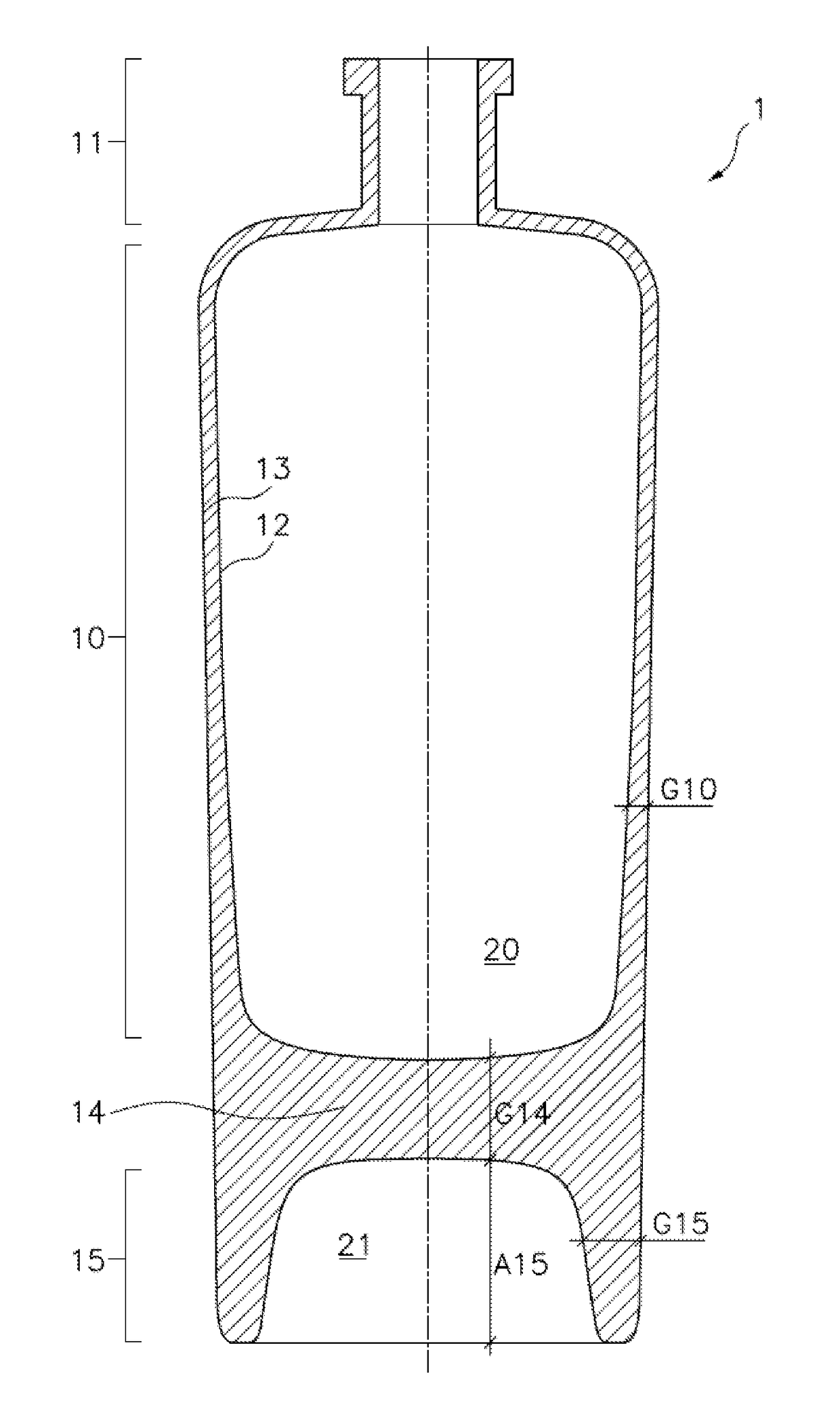
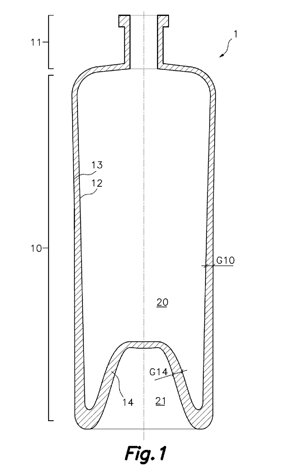
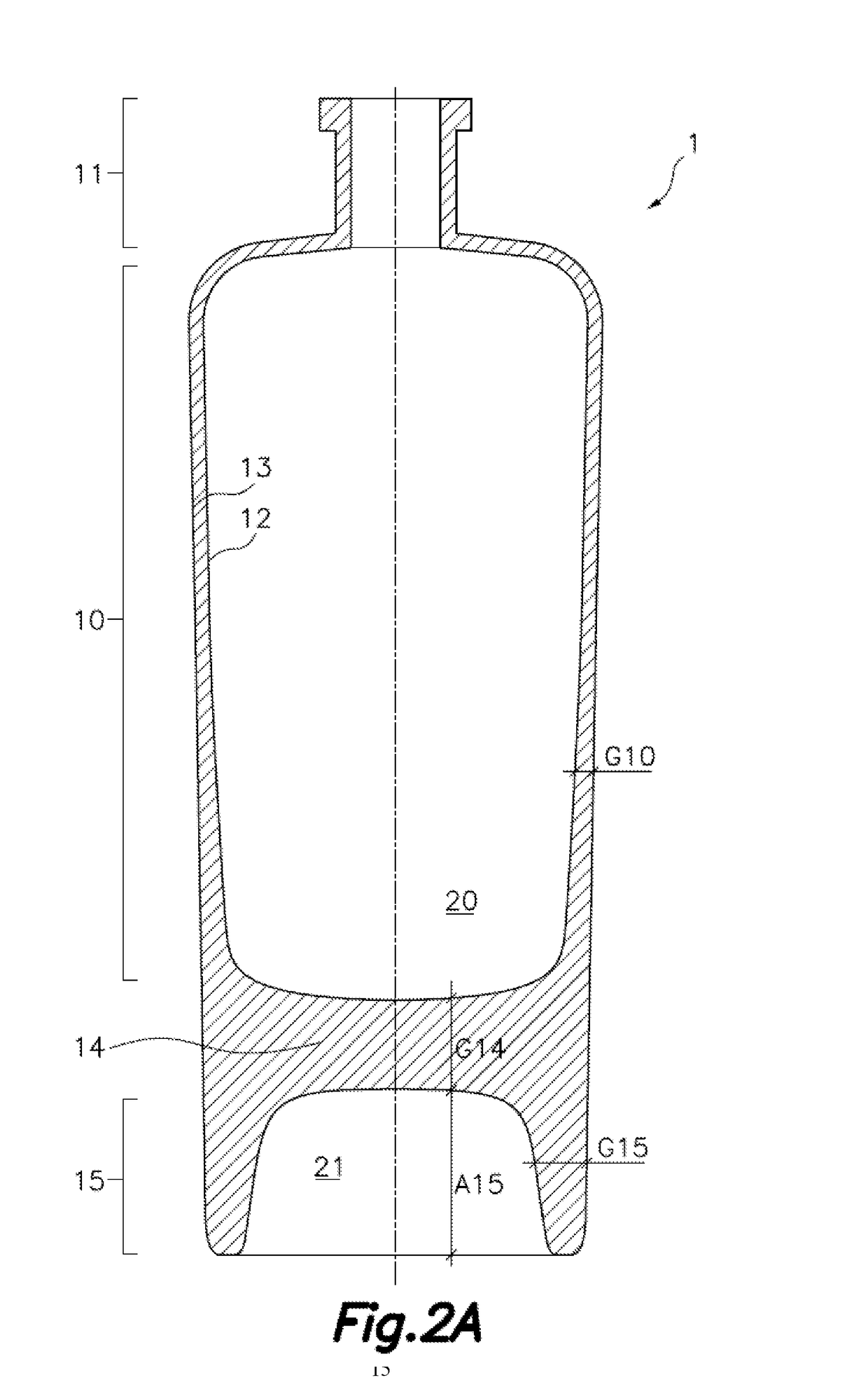
[0060]According to a non-limiting exemplary embodiments shown in FIGS. 2A and 2B, there is proposed a glass bottle 1 suitable for holding liquids, such as drinks or perfumes, said bottle 1 being formed by a neck 11 jointed in continuity to a receptacle tubular wall 10 through, for instance, transitional shoulders, and the receptacle tubular wall 10 being jointed in continuity to a bottom wall 14. The juncture of the neck 11, the receptacle tubular wall 10 and the bottom wall 14 defines the receptacle 20 therein destined to hold liquids.

[0061]The neck 11 is prepared to be capable of being hermetically sealed by means of a cap, in this exemplary embodiment by means of a cork cap inserted by means of force-fitting in said neck, but other materials, such as glass, are also very commonly used.

[0062]In the FIG. 2A exemplary embodiment, the receptacle tubular wall 10 is a hollow cylinder and the bottom wall 14 is circular, their diameters being coincident and the receptacle tubular wall 10...


PUM


Abstract

A glass bottle body made up by a neck jointed in continuity to a receptacle tubular wall, said bottle body being closed by a bottom wall placed on a bottle end side opposite regarding said neck, defining said bottom wall a receptacle capable of holding liquids, characterised in that said bottom wall is extended, in a perimeter area, by a base tubular wall that internally defines a cavity, said base tubular wall and the receptacle tubular wall being in opposite sides of the bottom wall; and the average height of the base tubular wall being equal to or larger than the average thickness of the base tubular wall, being the contents of the bottle highlighted by two laterally visible layers of the bottom of the bottle, producing a stand effect.

Description

FIELD OF THE ART[0001]The present invention relates to a glass bottle, the bottle being provided with a base tubular wall extended from the bottom wall of the bottle, rising the container and its contents.BACKGROUND OF THE INVENTION[0002]Glass bottles are traditionally formed by a receptacle tubular wall, which forms the body of the bottle and is jointed in continuity to a bottom wall, which closes the container, and said receptacle tubular wall is also jointed in continuity to a bottle neck by its part opposite to the base, typically prepared to be capable of being hermetically sealed by means of a cap, whether made of cork, plastic, metal, rubber, glass, and fitted whether by pressure, threadedly or using another material or method.[0003]Various bottom walls of glass bottles are known with different configurations and geometry, which typically have a swelling towards the inside of the bottle known in the art as punt, which confers them some characteristics of mechanical resistance...

Claims


Application Information

Patent Timeline
Patent Type & Authority Applications(United States)
IPC IPC(8): B65D1/02
CPCB65D1/0276B65D1/02B65D1/00B65D1/0207B65D1/0223B65D1/04
Inventor ARREGUI LETAMENDI, JOKIN
Owner DSIGNTANK SL
Why Eureka
Try Eureka