Method for manufacturing a denture

a manufacturing method and denture technology, applied in the field of denture manufacturing, can solve the problems of complex shapes, waste of a lot of materials, and complex manufacturing of dentures

Active Publication Date: 2017-09-28
3SHAPE AS
View PDF1 Cites 5 Cited by
  • Summary
  • Abstract
  • Description
  • Claims
  • Application Information

AI Technical Summary

Benefits of technology

[0020]The tooth receiving cavity formed by the through going hole and the bridge provides a stable pocket wherein the artificial tooth can be placed before the milling step. In particular it provides a larger gluing area wherein the artificial tooth can settle and cure before the bridge of excess material and the part of the tooth extending out of the through going hole is milled away to provide the seating surface.

Problems solved by technology

Denture manufacturing is very complex, and although the introduction of many digital processes have facilitated the manufacturing process, further improvement is still possible.
As 3D printing is an additive manufacturing process only the material needed is used in the process, whereas with milling which is a subtractive manufacturing process a lot of material is wasted as large volumes of unwanted material is removed with large objects.
Moreover, complex shapes such as a denture base as described herein often requires advanced milling machines such as five axis machines.
In some cases the seating surface provides a friction grip with the gingiva which allows the denture to be retained in the mouth of the patient, however, in other cases the denture is retained by implant or snap / ball coupling wherein the seating surface provides little effect in retaining the denture.
If the printing manufacturing device has very low tolerance it may even be necessary to rescan the intermediate denture base.

Method used


Image

  • Method for manufacturing a denture
  • Method for manufacturing a denture

Examples


Embodiment Construction

[0026]In the following description, reference is made to the accompanying figures, which show by way of illustration how the invention may be practiced.

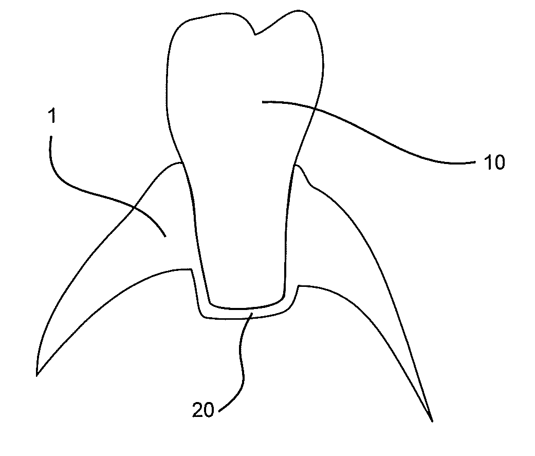
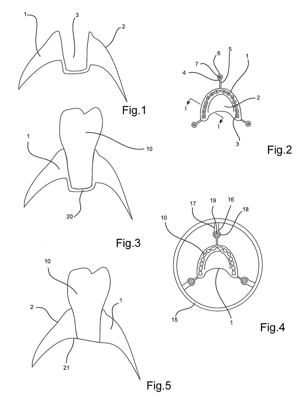
[0027]An intermediate denture base 1 is printed by using 3D printing techniques as known in the art. The intermediate denture base comprises an artificial gingiva surface 2. A tooth receiving cavity 3 is formed in intermediate denture base.

[0028]A sectional view of the intermediate denture base is shown in FIG. 1 and a top view of the intermediate denture base is shown in FIG. 2. The sectional view in FIG. 1 is seen along section I-I in FIG. 2. Three milling fixtures 4 are printed along with the denture base. The milling fixtures extend radially from the intermediate denture base and are formed by milling fixture arms 5 and a milling fixture attachment cylinder 6. The attachment cylinder is provided with a through going fixture bore 7.

[0029]After printing, artificial teeth 10 are placed in corresponding teeth receiving cavities 3. Th...


PUM

PropertyMeasurementUnit
shapeaaaaaaaaaa
volumesaaaaaaaaaa
pressureaaaaaaaaaa

Abstract

There is disclosed a method for manufacturing a denture comprising an artificial gingiva surface, a seating surface facing at least a part of the gingiva surface when placed in the mouth of a patient, at least one tooth receiving hole provided in the artificial gingiva surface and extending through to the seating surface and an artificial tooth arranged in the tooth receiving hole, The method comprises printing an intermediate denture base comprising the artificial gingiva surface, the at least one tooth receiving hole for receiving the artificial tooth, arranging the artificial tooth in the at least one tooth receiving hole, fixing the intermediate denture base in a milling machine, and milling the denture comprising providing the seating surface by removing at least a part of the tooth extending through the tooth receiving hole. This provides an improved manufacturing process of denture.

Description

FIELD OF THE INVENTION[0001]This invention generally relates to manufacturing a denture. In particular, it relates to a method that comprises printing of the denture base and subsequent milling thereof in order to take advantage of both techniques.BACKGROUND OF THE INVENTION[0002]Denture manufacturing is very complex, and although the introduction of many digital processes have facilitated the manufacturing process, further improvement is still possible.[0003]In particular, as will described herein a further improved manufacturing method may be obtained by using both 3D printing (additive manufacturing) and milling (subtractive manufacturing) in the manufacturing process.SUMMARY[0004]In one aspect the invention relates to a method for manufacturing a denture comprising an artificial gingiva surface, a seating surface facing at least a part of the gingiva surface when placed in the mouth of a patient, at least one tooth receiving hole provided in the artificial gingiva surface and ex...

Claims


Application Information

Patent Timeline
Patent Type & Authority Applications(United States)
IPC IPC(8): A61C13/01B29C67/00B33Y10/00B33Y80/00A61C13/00A61C13/36
CPCA61C13/01A61C13/0019A61C13/1016B29L2031/7536B33Y80/00B29C67/0051B33Y10/00
Inventor FISKER, RUNE
Owner 3SHAPE AS
Why Eureka
Try Eureka