
Electronic converter unit for retrofitting to an external part of a housing of a pump unit

a technology of electronic converter and pump unit, which is applied in the direction of heating types, space heating and ventilation details, domestic heating details, etc., can solve the problems of adding costs to the production price of the pump unit and thus to the purchase price of the end consumer, entail security risks, and it is difficult to extract more detailed information about the operating condition of the pump. , to achieve the effect of convenient removal, convenient relative alignment and efficient light emitted

Active Publication Date: 2017-09-21
GRUNDFOS HLDG
View PDF9 Cites 5 Cited by
  • Summary
  • Abstract
  • Description
  • Claims
  • Application Information

AI Technical Summary

Benefits of technology

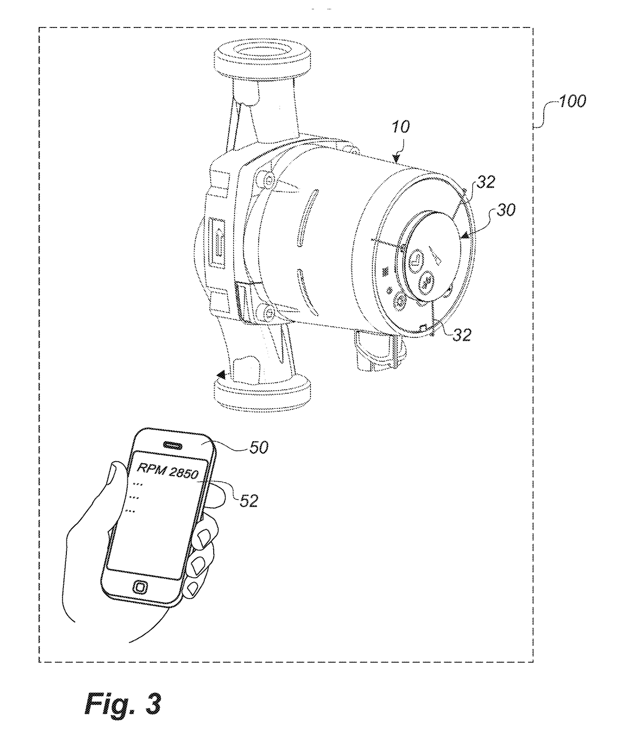
The patent invention allows a user to view information about the status of a pump using their smart phone. This is achieved by using a converter device and a handheld communication device to access the pump unit, eliminating the need for an expensive user interface on the pump. This reduces the manufacturer's production cost and the end consumer's purchase cost. The electronic converter unit communicates unidirectionally with the pump unit and can also communicate with the handheld device in either a unidirectional or bi-directional manner. The use of optical readouts and RFID or NFC based communication allows for the display on the pump unit to be simplified, and the use of a retrofitted electronic converter unit provides improved security aspects.

Problems solved by technology

However, providing a pump unit with a display or a touch screen adds costs to the production price of the pump unit and thus also to the purchase price of the end consumer.
Further, it entails a security risk, if anybody can gain access to the control system and to control the system to drive the pump unit at erroneous drive conditions.
While a simple diode display may provide a simple visual indication to a user, e.g. green light for correct operating conditions and red light for faulty operating conditions, it is difficult to extract more detailed information about the operating condition of the pump.
Further, the pump unit is usually provided with an energy-saving switch-mode converter or power supply, and switch-mode noise may thus influence external instruments.

Method used


Image

  • Electronic converter unit for retrofitting to an external part of a housing of a pump unit
  • Electronic converter unit for retrofitting to an external part of a housing of a pump unit
  • Electronic converter unit for retrofitting to an external part of a housing of a pump unit

Examples


Embodiment Construction

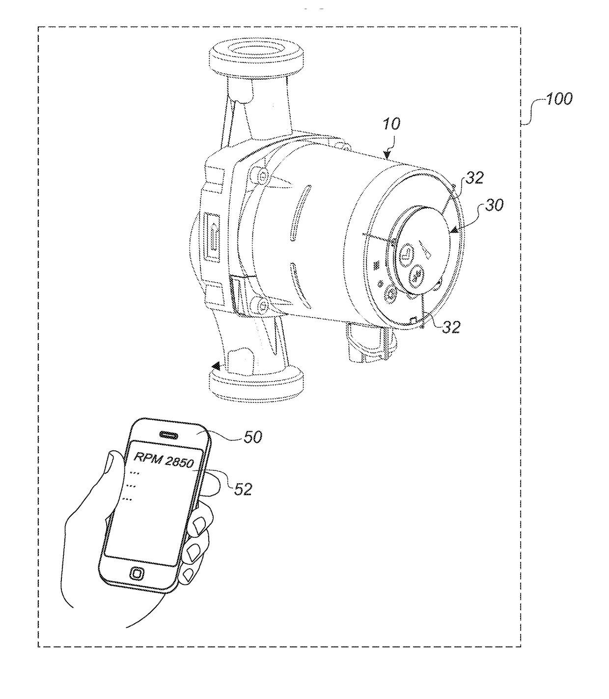
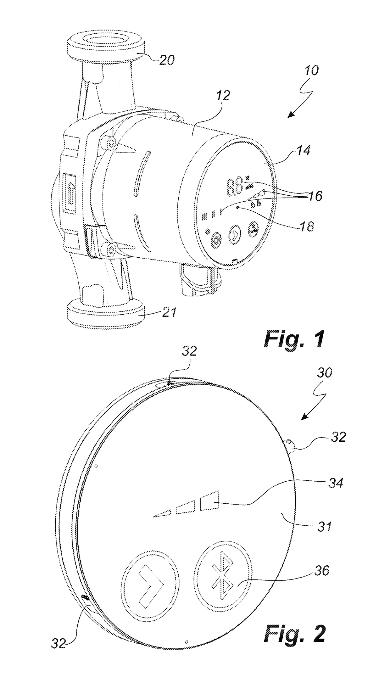
[0099]FIG. 1 shows a perspective view of a pump unit 10 or pump assembly. The pump unit comprises a housing 12 or terminal box, which has a front end 14 or display, which may be provided with a number of display units 16, which may provide a simple indication of an operating status of the pump unit. However, the invention also makes it possible to simplify the front end 14 even further, as the necessity of having a display is alleviated, whereby the production cost and thereby the price for the end-consumer may be lowered considerably. Accordingly, the front end 14 may be provided without the display units 16. The front end 14 is further provided with a light source 18, e.g. in form of a single photo diode or a plurality of photo diodes. The pump unit 10 is under operation installed in a pipe system via the pipe flanges 20, 21.

[0100]The housing 12 or terminal box of the pump unit 10 houses an electrical motor and a drive shaft as well as control circuitry of the pump unit 10. In the...


PUM


Abstract

An electronic converter unit for retrofitting to an external part of a housing of a pump unit is described. The housing comprises a light source for emitting light to display an operating status of the pump unit. The electronic converter unit comprises: a photo detector for measuring light emitted from the light source of the pump unit, a converter unit for converting optical signals to electrical signals, and transmitting means for wirelessly transmitting the electrical signals to an external communication unit.

Description

FIELD OF THE INVENTION[0001]The present invention relates to an electronic converter unit for retrofitting to an external part of a housing of a pump unit, such as a centrifugal pump. The invention further relates to a kit of parts comprising a pump unit and an electronic converter unit. The invention additionally relates to a system comprising a pump unit, an electronic converter unit, and an external communication device, such as a smart phone. Finally, the invention relates to a method for checking the operating status of a pump unit on an external communication unitBACKGROUND OF THE INVENTION[0002]Many modern pump systems are provided with various types of controls in order to control pump units in specific ways. Circulation pumps are often intended to deliver a specific head and flow rate at given circumstances in order to meet particular requirements. To meet the different requirements, the pump units may be controlled according to different control patterns by changing one or...

Claims


Application Information

Patent Timeline
IPC IPC(8): H04Q9/00F04D13/06F04D15/00
CPCH04Q9/00F04D15/0088H04Q2209/43F04D15/0066F04D13/0686F24D19/1015H04L12/1854H04W84/18F24D19/1048F24D19/1012F24D3/10Y02B30/70H04Q2209/00H04Q2209/40
Inventor BERGQVIST, RENE STIGWOLF, CHRISTIANMILTHERS, JENS
Owner GRUNDFOS HLDG
Learn More