Electronic timepiece with electrostatic induction generator

a technology of electrostatic induction generator and electronic watch, which is applied in the direction of influence generators, instruments, horology, etc., can solve the problems of low useable energy density inside a room, inability to obtain continuous energy, and often mistakenly believe that the power generation has broken down, so as to reduce instances, efficiently rotate, and easily recognize the state of power generation

Active Publication Date: 2017-09-21
CITIZEN WATCH CO LTD
View PDF5 Cites 7 Cited by
  • Summary
  • Abstract
  • Description
  • Claims
  • Application Information

AI Technical Summary

Benefits of technology

[0017]As shown in FIG. 2, it is possible to visually confirm rotational of the rotary member 4 from the outside, so a user can easily recognize the state of power generation. Further, the rotary member 4 is formed with radially cut parts etc. and is interesting visually. Rotation, as shown in FIG. 2, creates interest in the user over the state of power generation thanks to the design, so the user can be prompted to continually generate power. Further, the user can visually confirm rotational of the rotary member 4 from the outside while learning what kind of movement enables the rotary member 4 to efficiently rotate when carried. Due to this, the present invention not only makes it possible to visually confirm operation from the outside and therefore reduce instances of the power save mode being mistakenly understood, but also makes it possible to keep a user conscious of the operating state when carried and thereby enables power to be efficiently generated and the chance of insufficient power to be greatly reduced.

Problems solved by technology

A power generation device such as a solar cell module has the problem that the density of useable energy inside a room is low except when under direct sunlight and further that continuous energy cannot be obtained.
An electronic watch entering such a power save mode ends up with the liquid crystal display extinguished and the hands stopped, so the user often mistakenly believes it has broken down.
However, not only does the cost increase by the amount of provision of the display means, but also it becomes necessary to secure space for the display of the display means.
There was the problem that the size of the watch ended up becoming larger by that amount.
Further, when the level of charge of the secondary battery became lower and became the power becomes insufficient, it became necessary to place the solar cell module in direct sunlight to charge it and confirm operation.
This often led to failure to immediately judge breakdown.
When applying these power generating devices to portable electronic watches, in the same way as the solar cell modules and other electronic watches or clocks explained above, the above problem arises that the user will frequently end up misconstruing the power save mode as a breakdown.
For this reason, in the power save mode or when the charge of the secondary battery becomes low and therefore power becomes insufficient, the user could not immediately confirm the state of power generation.

Method used


Image

  • Electronic timepiece with electrostatic induction generator
  • Electronic timepiece with electrostatic induction generator
  • Electronic timepiece with electrostatic induction generator

Examples


first embodiment

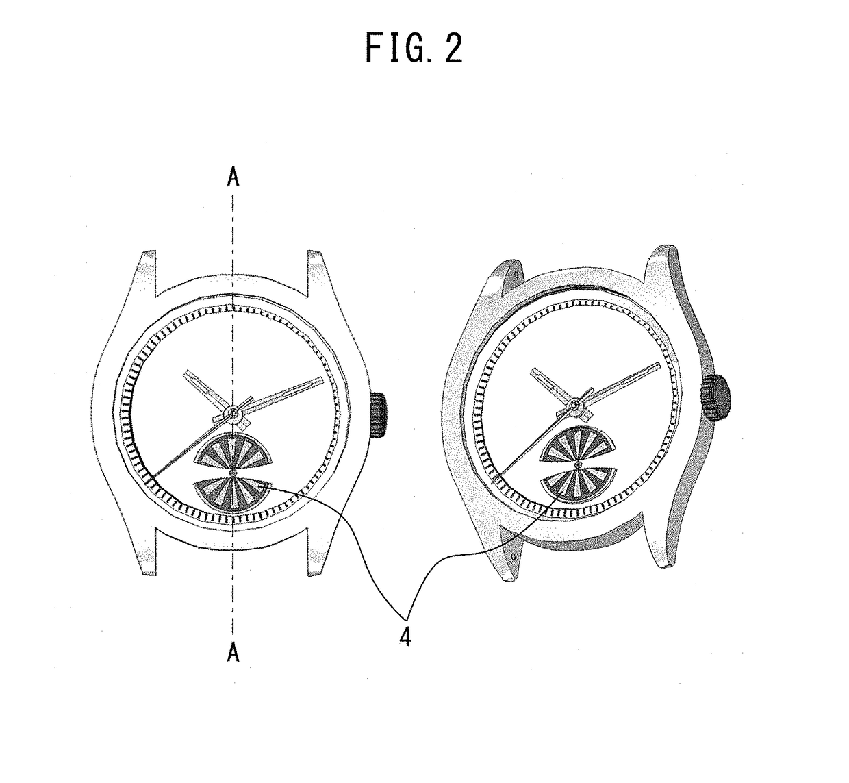
[0044]FIG. 3 is a schematic cross-sectional view along the line A-A of FIG. 2 showing a first embodiment of the present invention. FIG. 4 is a plan view of a main plate of the first embodiment of the present invention. FIG. 5 gives an outline showing an internal structure of the first embodiment of the present invention. FIG. 6 is a partial perspective view for explaining the first embodiment of the present invention. FIG. 7 is a view showing patterns of a counter electrode 2 and charging film 3 of the first embodiment of the present invention. FIG. 8 is a view showing other patterns of a counter electrode 2 and charging film 3 of the first embodiment of the present invention. In the cross-sectional view of FIG. 3, the protective glass 24 side is called the “top part”, the “top side”, and “above”, while the case back 42 side is called the “bottom part”, “bottom side”, and “below”.

[0045]Below, the first embodiment will be explained with reference to the drawings. The present embodime...

second embodiment

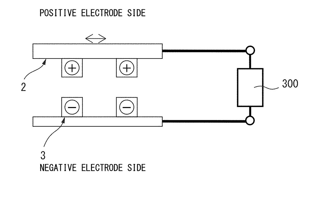
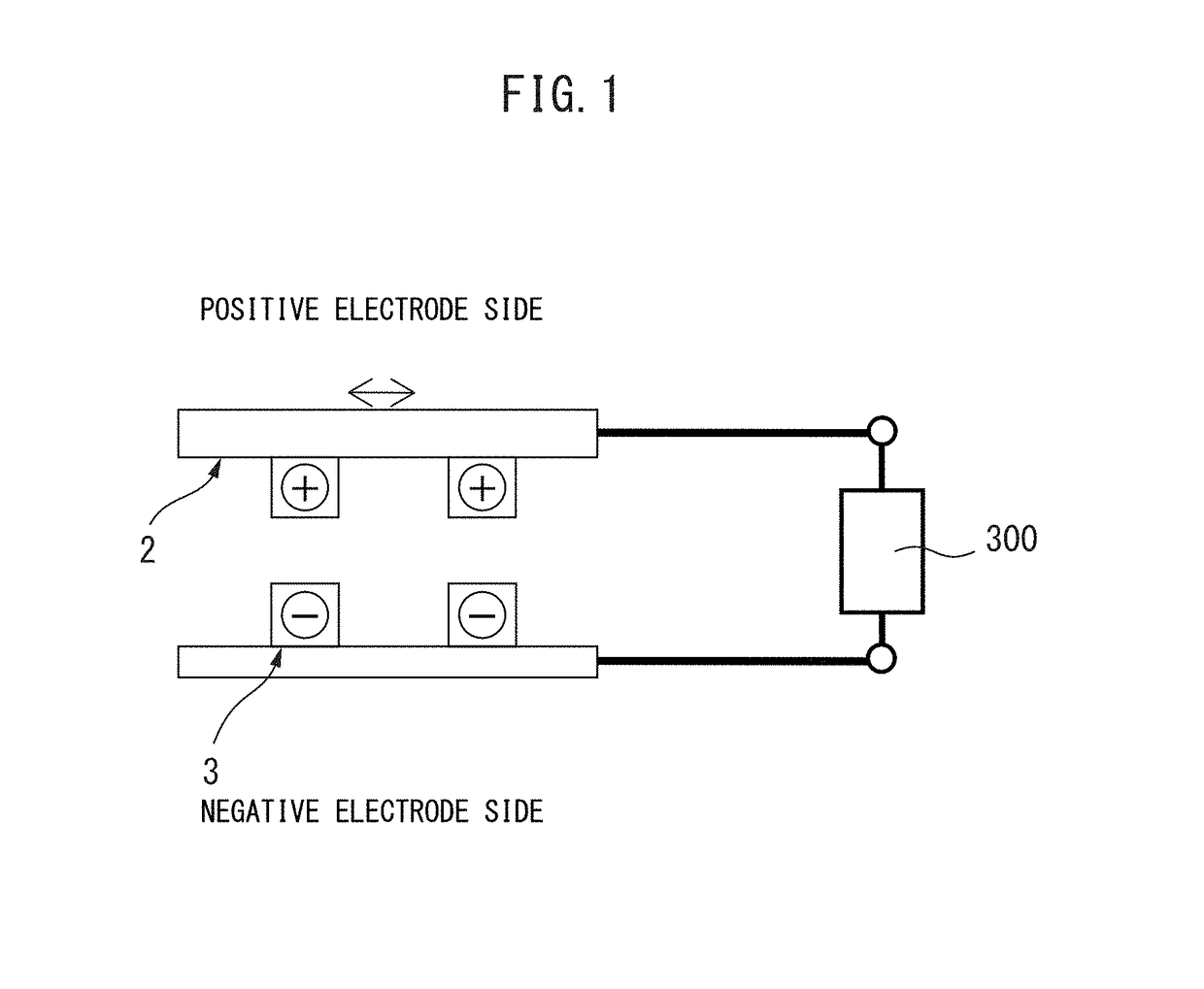
[0064]The second embodiment of the present invention has the counter electrode 2 placed on the bottom surface of the rotary member 4 in the first embodiment of FIG. 3 instead of the charging film 3, and has the charging film 3 placed on the top surface of the counter substrate 1 instead of the counter electrode 2. The rest of the configuration is similar to the first embodiment. Therefore, in the present embodiment, the window part 51 of the dial plate 25, the window part 52 of the main plate 33, rotary member 4, counter electrode 2, charging film 3, counter substrate 1, and bridge 34 are arranged in that order from the top part toward the bottom part. For the patterns of the counter electrode 2 and charging film 3, the first patterns of FIG. 7 are employed. The counter electrode 2 takes out an output terminal from the shaft 8 to which the rotary member 4 is fastened and takes out an output terminal from the charging film 3 set on the top surface of the stationary counter substrate ...

third embodiment

[0069]FIG. 10 is a schematic cross-sectional view showing a third embodiment of the present invention.

[0070]Referring to FIG. 10, the configuration of an electrostatic induction generator will be explained. The difference from the first and second embodiments explained up to here is the point of provision of the counter substrate 1 at the window part 52 side. For this reason, the counter substrate 1 is made a glass or other light passing member. For the counter electrode 2, a light passing indium tin oxide film (ITO film) or other transparent electrode is used. Due to this, it is possible to visually confirm the rotation of the rotary member through the window part 51 of the dial plate 25 and the window part 52 of the main plate 33. The rest of the configuration is similar to the first embodiment explained previously.

[0071]After the window part 52 of the main plate 33, the counter substrate 1 is placed and set (while explained later, conveniently at the time of assembly). In the pre...


PUM


Abstract

An electronic watch or clock with an electrostatic induction generator, wherein the electrostatic induction generator has a rotary weight able to rotate with respect to a housing, a rotary member able to rotate with respect to the housing, a counter substrate fastened to the housing, a charging film arranged at one of the rotary member and counter substrate, and a counter electrode arranged facing the charging film at the other, outputs electric power generated between the charging film and the counter electrode to a quartz movement, and provides a window part at one or more locations among the dial plate, housing, or outside casing to enable rotation of the rotary member or transmission of rotation to be visually confirmed.

Description

TECHNICAL FIELD[0001]The present invention relates to an electronic watch, clock or timepiece with an electrostatic induction generator designed to enable a user to check the state of power generation.BACKGROUND ART[0002]A wristwatch or other portable electronic clock containing a solar cell module or other power generation device and operating without having to replace batteries has been realized. A power generation device such as a solar cell module has the problem that the density of useable energy inside a room is low except when under direct sunlight and further that continuous energy cannot be obtained. For this reason, a watch has a power save function whereby it automatically enters a power conserving state when detecting that light is not striking the solar cell module and power has not been generated for a certain time. Further, as shown in PLT 1, even an electronic watch with an electromagnetic induction generator which captures movement of a user's arm etc. to convert ki...

Claims


Application Information

Patent Timeline
Patent Type & Authority Applications(United States)
IPC IPC(8): G04G19/00G04C10/02
CPCG04C10/02G04G19/00G04C10/00H02N1/08G04G17/00
Inventor IHARA, TAKASHIIZUMI, AKIRAWATANABE, MAKOTO
Owner CITIZEN WATCH CO LTD
Why Eureka
Try Eureka