Apparatus and method for forming a polymeric web

Active Publication Date: 2017-09-21
POLY AMERICA
View PDF3 Cites 7 Cited by
  • Summary
  • Abstract
  • Description
  • Claims
  • Application Information

AI Technical Summary

Benefits of technology

The present invention is about an apparatus and method for making a multi-layered polymeric web from multiple collapsed tubes of polymeric film. The apparatus includes a first source of a first molten polymer and a second source of a second molten polymer. A blown film extrusion die has an outer and inner die lip and is surrounded by an outer and inner inner die lip. The first molten polymer is extruded upwardly out of the outer die lip to form an outer polymeric film tube with an outer frost line. The second molten polymer is extruded upwardly out of the inner die lip to form an inner polymeric film tube with an inner frost line. The inner and outer polymeric film tubes are collapsed so that they are placed into intimate contact with each other without bonding to each other. The apparatus can produce a multi-layered polymeric web with different characteristics and colors in the outer and inner layers. The technical effects of the invention include improved production efficiency, control over film thickness, and improved quality of the finished product.

Problems solved by technology

Without an IBC assembly, the bubble contains a static volume of air applying outward pressure on the plastic film tube but there is no avenue to dissipate the heat absorbed by the static volume of air from the plastic film tube.
Consequently, the interior air volume quickly settles at approximately the same temperature as the plastic film tube, providing no cooling benefit.
However, it is known that certain material properties of the laminate negatively influence the material properties of the laminate.
Hence, when tear strength is a critical property for a web, it is undesirable to form a coextruded film with a resin having a low tear strength with another resin having a relatively strong tear strength, even though such a combination may provide other desirable properties.
However, The Borchardt Application fails to disclose allowing both bubbles to fully cool below the molten state before coming into contact with each other.
The Borchardt Application also fails to address the decrease in throughput typical of extruding multiple layers due to the difficulties presented in adequately cooling the multiple tube of polymeric film to maintain an acceptable frost line elevation.

Method used


Image

  • Apparatus and method for forming a polymeric web
  • Apparatus and method for forming a polymeric web
  • Apparatus and method for forming a polymeric web

Examples


Embodiment Construction

[0029]The present disclosure illustrates one or more embodiments of the present invention. It is not intended to provide an illustration or encompass all embodiments contemplated by the present invention. In view of the disclosure of the present invention contained herein, a person having ordinary skill in the art will recognize that innumerable modifications and insubstantial changes may be incorporated or otherwise included within the present invention without diverging from the spirit of the invention. Therefore, it is understood that the present invention is not limited to those embodiments disclosed herein. The appended claims are intended to more fully and accurately encompass the invention to the fullest extent possible, but it is fully appreciated that certain limitations on the use of particular terms is not intended to conclusively limit the scope of protection.

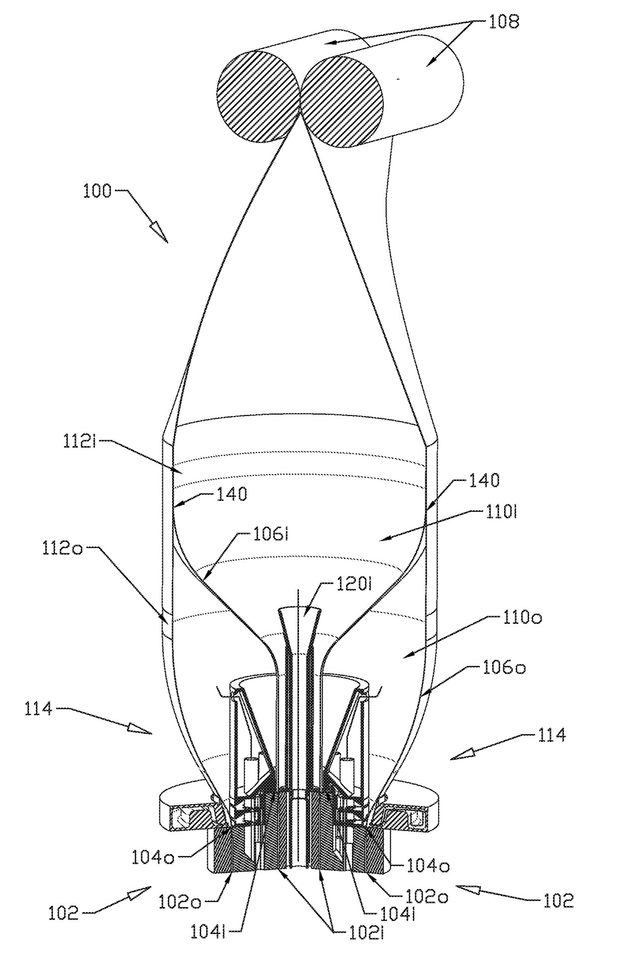
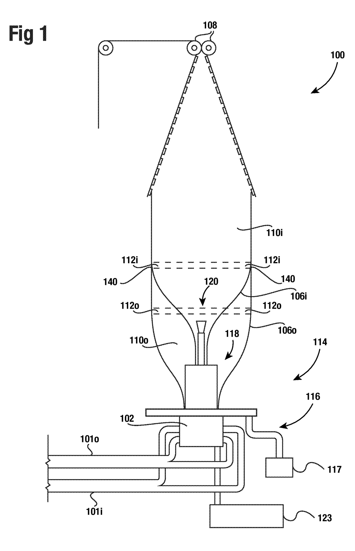
[0030]FIG. 1 illustrates a schematic overview of a blown film extrusion system 100, according to one embodiment o...


PUM

PropertyMeasurementUnit
Coloraaaaaaaaaa
Heightaaaaaaaaaa
Polymericaaaaaaaaaa

Abstract

The present invention is directed to an apparatus for forming a multi-layer web formed from at least two polymeric film tubes in intimate contact with each other but not bonded to each other. The apparatus and method includes the use of a blown film extrusion die that extrudes two separate blown film polymeric tubes via two separate annular die lips. A fluid cooling system applies cooling fluid across a plurality of surfaces of the two blown film tubes. One of the die lips may be at a different height from the other die lip. The frost line of one blown film tube may be at a different height from the other blown film tube.

Description

CROSS-REFERENCE TO RELATED APPLICATIONS[0001]Not applicable.BACKGROUND OF THE INVENTION[0002]1. Field of the Invention[0003]This invention relates generally to an apparatus and method for forming a multilayer polymeric web from two or more polymeric film tubes formed from a single blown film extrusion die. More particularly, this invention relates to an apparatus and method for forming and cooling at least pair of molten plastic film tubes exiting a pair of outlet lips of an extrusion die in a blown film process to form a continuous web comprising multiple layers of film.[0004]2. Description of the Related Art[0005]Thin plastic film may be produced, in addition to other manufacturing methods, by extruding plastic material, such as polyethylene resin or other similar polymeric resins, in a process known as blown film extrusion. In a typical blown film extrusion process, resin is fed into a single extruder where an extrusion screw pushes the resin through the extruder. The extrusion s...

Claims


Application Information

Patent Timeline
IPC IPC(8): B29C47/00B29C47/08B29C48/10
CPCB29C47/0021B29C47/08B29L2009/00B29L2007/008B29K2023/04B29C48/10B29C48/0015B29C48/0018B29C48/17B29C48/21B29C48/0255B29C48/32B29C48/335B29C48/362B29C48/387B29C48/70B29C48/912B29C48/08B29C48/25
Inventor WOOD, GREGORY JAMESCOBLER, BRAD A.
Owner POLY AMERICA
Why Eureka
Try Eureka