
Multi-head array fire sprinkler system with heat shields

a sprinkler system and array technology, applied in the field of sprinklers, can solve the problems of not taxing the limited available water supply, and achieve the effects of improving hydraulic efficiency, improving control, and quickening response times

Active Publication Date: 2017-09-14
FIREBIRD SPRINKLER COMPANY
View PDF11 Cites 7 Cited by
  • Summary
  • Abstract
  • Description
  • Claims
  • Application Information

AI Technical Summary

Benefits of technology

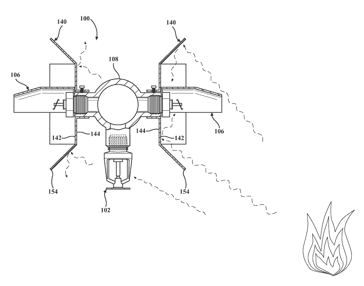
This patent is for a system that helps firefighters use water more efficiently by controlling the placement of sprinklers. The system uses lateral heat shields that help direct water to the flames faster, while slowing down other sprinklers that may not be needed. This maximizes the amount of water pressure and increases the coverage area and water velocity, making it easier to put out the fire. The system also makes it easier to control the fire suppression, reducing labor and material costs.

Problems solved by technology

Because of the lateral heat shields, the water pressure required to fight a fire will be maximized by retarding activation of unwanted sprinklers and thereby not taxing the limited available water supply.

Method used


Image

  • Multi-head array fire sprinkler system with heat shields
  • Multi-head array fire sprinkler system with heat shields
  • Multi-head array fire sprinkler system with heat shields

Examples


Embodiment Construction

[0044]Referring to the figures, wherein like numerals indicate like or corresponding parts throughout the several views, a fire suppression system according to one exemplary expression of the present invention is generally shown at 20 in FIGS. 3-9. In FIG. 3, the fire suppression system 20 is shown located in the interior storage space of a building structure. The building structure may be a warehouse having a floor 22, and at least three beams 24 suspended over the floor 22. The beams 24 are preferably steel I-shaped rafters, but may be any suitable structural member made from any suitable material and shaped in any suitable manner. The beams 24 are typically arranged parallel to one another and spaced evenly apart by an interior bay length L1. In this example, the three beams 24 may be consider first, second and third beams 24, with the second beam being disposed in between the first and third beams 24. Each beam 24 is supported by a pair of substantially vertical uprights or post...


PUM


Abstract

A fire suppression system in which the water supply line is fitted with repeating arrays or groups of sprinkler heads. Each array is composed of at least two side-discharge sprinklers. The side-discharge sprinklers in each array are aimed so that their coverage areas point in opposite directions. Each side-discharge sprinkler includes a lateral heat shield. The lateral heat shield has a concave heat-concentering side that focuses radiant heat toward the sprinkler's trigger, and a convex heat-scattering side that disperses radiant heat away from the trigger. In some embodiments, the array can include one or more vertical-discharge sprinklers. The vertical-discharge sprinkler may include a heat collector to facilitate early activation of its trigger.

Description

CROSS REFERENCE TO RELATED APPLICATIONS[0001]This application is a Continuation-in-Part of U.S. application Ser. No. 15 / 257,961 filed Sep. 7, 2016, which claims priority to Provisional Patent Application No. 62 / 215,058 filed Sep. 7, 2015, and is a Continuation-in-Part of U.S. application Ser. No. 14 / 661,302 filed Mar. 18, 2015, which claims priority to Provisional Patent Application No. 61 / 955,253 filed Mar. 19, 2014 and to Provisional Patent Application No. 62 / 019,527 filed Jul. 1, 2014, the entire disclosures of which are hereby incorporated by reference and relied upon.BACKGROUND OF THE INVENTION[0002]Field of the Invention[0003]The invention relates generally to methods and systems for extinguishing fires, and more particularly to sprinklers of such systems.[0004]Description of Related Art[0005]Fire suppression systems have been used in the United States to protect warehouses and factories for many years. In a fire suppression system, a fire sprinkler is positioned near the ceil...

Claims


Application Information

Patent Timeline
Patent Type & Authority Applications(United States)
IPC IPC(8): A62C35/68A62C35/64A62C37/11B05B1/26A62C3/00A62C31/02
CPCA62C35/68A62C3/002A62C35/64A62C37/11B05B1/267A62C31/02
Inventor PIGEON, JEFFREY J.
Owner FIREBIRD SPRINKLER COMPANY
Learn More