Method for Determining the Position of a Magnet Relative to a Row of Sensors

a technology of magnet position and sensor row, applied in the direction of measuring devices, instruments, using electrical means, etc., can solve the problems of calculation effort which has to be employed, and achieve the effects of improving the unique nature of sensor signals, reducing the field strength, and reducing the number of ambiguities

Active Publication Date: 2017-09-07
TE CONNECTIVITY SENSORS GERMANY GMBH
View PDF6 Cites 2 Cited by
  • Summary
  • Abstract
  • Description
  • Claims
  • Application Information

AI Technical Summary

Benefits of technology

The patent describes a design for a magnetic sensor that reduces the need for additional calculations and improves the accuracy of the sensor signals. The sensors are arranged with their preferred direction facing the magnet, which helps to make the signals comparable. The position of the magnet can be determined by the value of the leading signal or a value derived from it. A magnetic support field is used to improve the unique nature of the sensor signals and make a larger unambiguously evaluable measuring region possible using a smaller number of sensors. The magnet has a magnetization that points in a direction parallel to the row direction or in the opposite direction. The use of a support field strengthened in the direction of the row direction can lead to a strengthening of the support field and reduce ambiguities in the sensor signals, but it also deteriorates the modulation of the sensor and increases offset errors and drift.

Problems solved by technology

A possible disadvantage with the present method can be the calculation effort which has to be employed in order to establish in the evaluation unit the amount by which and the direction in which the progression of the sensor signal and the progression of the reference signal have to be displaced relative to one another in order to achieve congruence between the sensor signal and the reference signal.

Method used


Image

  • Method for Determining the Position of a Magnet Relative to a Row of Sensors
  • Method for Determining the Position of a Magnet Relative to a Row of Sensors
  • Method for Determining the Position of a Magnet Relative to a Row of Sensors

Examples


Embodiment Construction

)

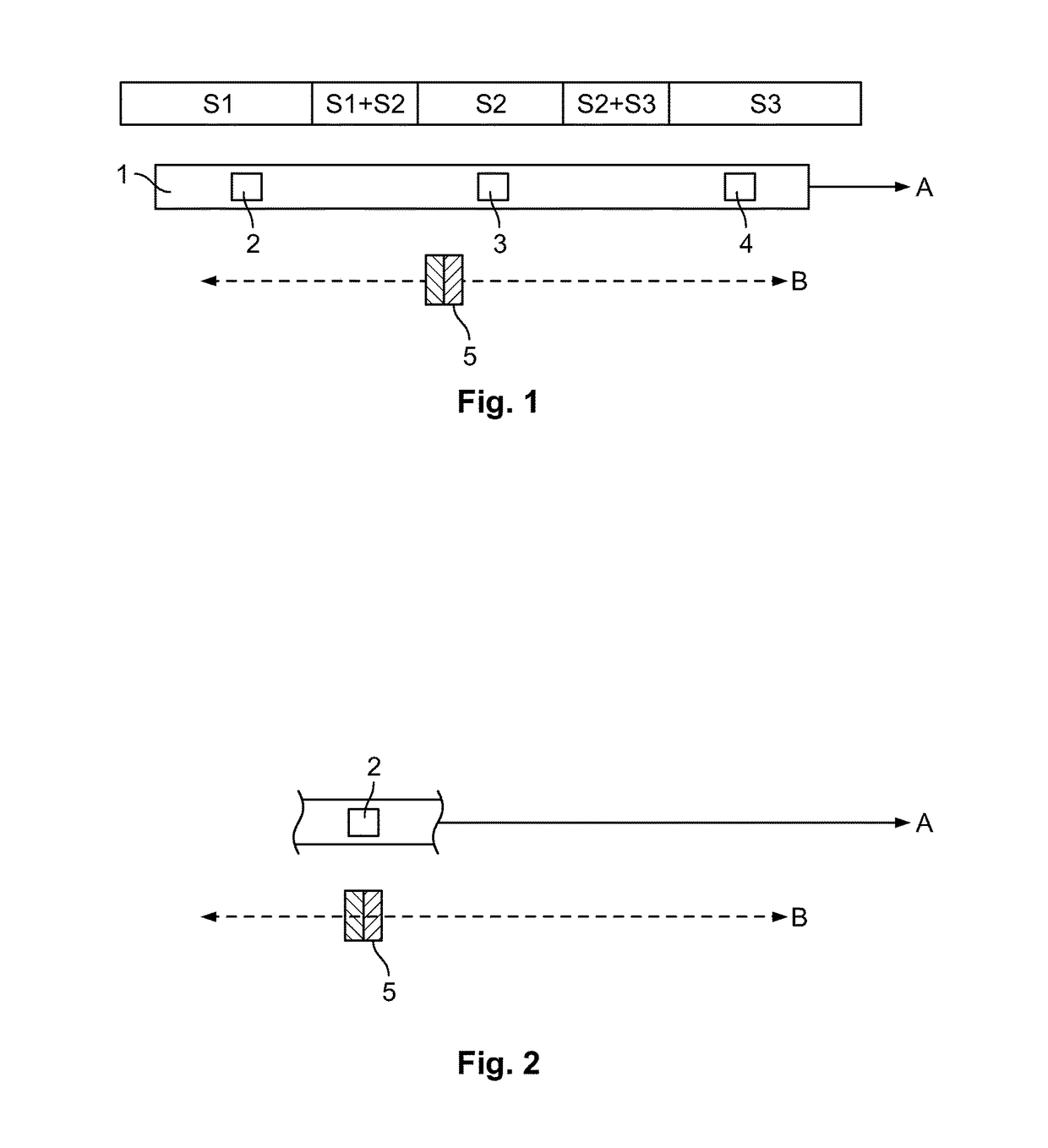
[0072]The device shown in FIG. 1 has a row of sensors 1. A first magnetic-field sensor 2, a second magnetic-field sensor 3 and a third magnetic-field sensor 4 are arranged on the row of sensors, spaced apart from one another in row direction A. The embodiment depicted in FIG. 1 is a row of sensors 1 which extends linearly. Additional sensors which are not depicted can follow the third sensor 4 in row direction A.

[0073]The device has a magnet 5. It can be moved relative to the row of sensors in the direction of the double arrow B and thus in a direction parallel to row direction A.

[0074]The magnet generates a magnetic field (not depicted in greater detail), wherein, in the embodiment depicted here, the direction of magnetization of the magnet (the direction pointing from the north pole to the south pole of the magnet) corresponds to the direction of movement B of the magnet 5 and thus runs parallel to the row direction A.

[0075]Five regions are indicated by shading above the row of s...


PUM


Abstract

The invention relates to a method for determining the position that a magnet has at a time of measurement relative to a row of sensors extending in a row direction, wherein the position of the magnet relative to the row of sensors can be changed in the direction of the row direction or in the direction parallel to the row direction, wherein the row of sensors has a first magnetic-field-sensitive sensor and a second magnetic-field-sensitive sensor, which is arranged spaced apart from the first sensor in the row direction, wherein a first sensor signal is generated by the first sensor, the value of which, at the time of measurement, depends on the position of the magnet relative to the first sensor at the time of measurement, and a second sensor signal is generated by the second sensor, the value of which, at a time of measurement, depends on the position of the magnet relative to the second sensor at the time of measurement, wherein, in a first examination, the value that the first sensor signal has generated at the time of measurement is compared with a first reference value and / or is checked as to whether it belongs to a first value range, in a second examination, the value that the second sensor signal has generated at the time of measurement is compared with a second reference value and / or is checked as to whether it belongs to a second value range, a relative value is formed from the value that the first sensor signal has generated at the time of measurement and the value that the second sensor signal has generated at the time of measurement, and, in a third examination, this relative value is compared with a third reference value and / or is checked as to whether it belongs to a third value range, and from the result of the first examination and the result of the second examination and the result of the third examination, a determination is carried out as to which of the sensor signals should be regarded as the leading signal for the time of measurement, wherein the position of the magnet relative to the row of sensors at the time of measurement is determined by evaluating the leading signal determined in this manner.

Description

CROSS-REFERENCE TO RELATED APPLICATION[0001]This application claims the benefit of the filing date under 35 U.S.C. §119(a)-(d) of German Patent Application No. 102016002420.8 filed Mar. 2, 2016.FIELD OF THE INVENTION[0002]The invention relates to a method for determining the position of a magnet a time of measurement relative to a row of sensors.BACKGROUND[0003]From DE 10 2010 025 170 B4 there is known a method for determining the position of a magnet at a time of measurement relative to a row of sensors extending in a row direction. The position of the magnet relative to the row of sensors can be changed in a direction parallel to the row direction, wherein the row of sensors has a first magnetic-field-sensitive sensor and a second magnetic-field-sensitive sensor, which is arranged, spaced apart from the first sensor in the row direction. In the method known from DE 10 2010 025 170 B4, in one preferred embodiment it is possible for sensors to be employed which are each constructed ...

Claims


Application Information

Patent Timeline
Patent Type & Authority Applications(United States)
IPC IPC(8): G01D5/20
CPCG01D5/2033G01D5/145G01B7/14G01D5/12G01D5/16
Inventor VOSS, ANDREASBORGES, OLIVERMEISENBERG, ARMINBARTOS, AXEL
Owner TE CONNECTIVITY SENSORS GERMANY GMBH
Why Eureka
Try Eureka