Radio communication system and communication control method
- Summary
- Abstract
- Description
- Claims
- Application Information
AI Technical Summary
Benefits of technology
Problems solved by technology
Method used
Image

Examples
first example
1.2) First Example
[0058]A first example of the communication control method according to the first illustrative embodiment shows the case of ePDCCH with JT CoMP, which will be described by referring to FIGS. 8A and 8B.
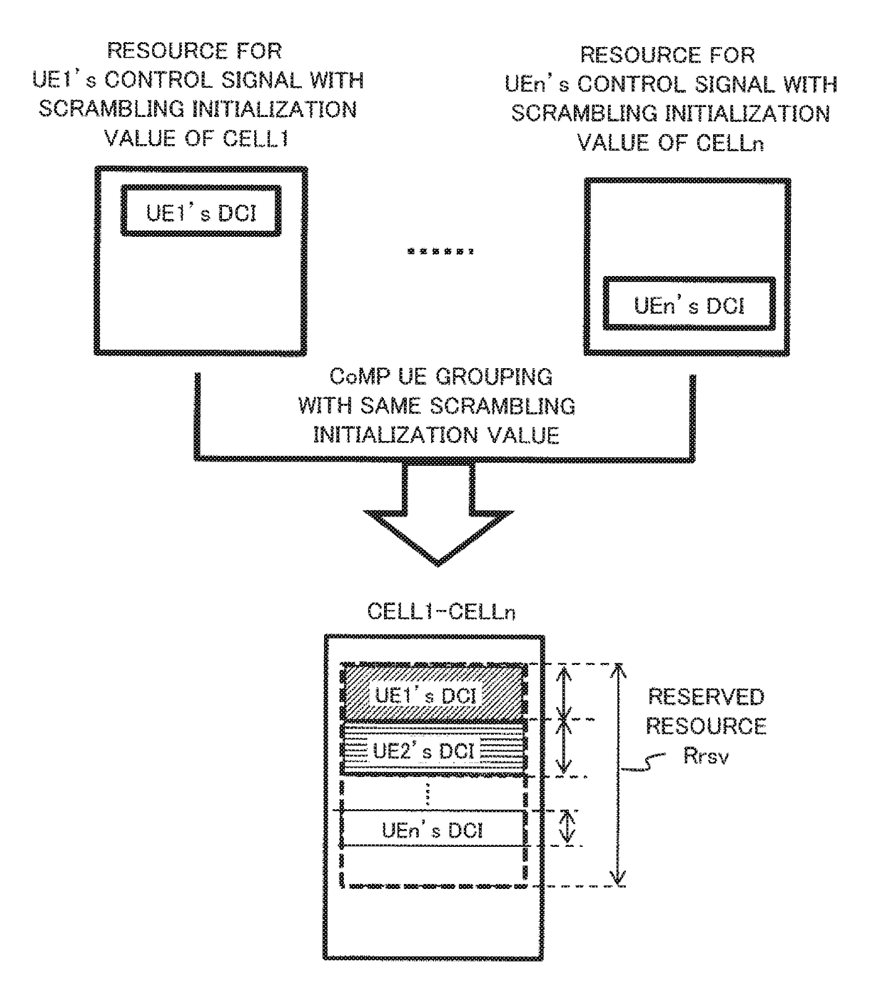
[0059]As shown in FIG. 8A, JT CoMP is applied to send ePDCCH of CoMP UE group from multiple selected TPs (TxRx units 21 and 22). Here, JT CoMP is also applied to data transmission over PDSCH for UE1 and UE2. The TxRx units 21 and 22 (Cell1 and Cell2) are the selected TPs, simultaneously transmitting both data and control signal to UE1 and UE2. For ePDCCH, a common scrambling initialization value cinit is needed and a common radio resource region Rrsv is reserved for UE1 and UE2.
[0060]As shown in FIG. 8B, over reserved resource region Rrsv, same RBs as well as REs are allocated for each UE's DCI at both Cell1 and Cell2 (TxRx units 21 and 22). In case of precoding of joint transmission, the PMI and RI at Cell1 and Cell2 need to be decided based on the UE feedback CSI. Fo...
second example
1.3) Second Example
[0061]A second example of the communication control method according to the first illustrative embodiment shows the case of ePDCCH with DPS, which will be described by referring to FIGS. 9A and 9B.
[0062]As shown in FIG. 9A, DPS CoMP is applied to send ePDCCH of the CoMP UE group from one dynamically selected TP (TxRx unit). The process is similar to that of ePDCCH with JT CoMP given in FIGS. 8A and 8B, except that only one TP (TxRx unit) is dynamically selected for sending PDSCH and ePDCCH. Although the common radio resource region Rrsv is reserved at both Cell1 and Cell2 (TxRx units 21 and 22), the control section 107 only allocates RBs and REs within the reserved radio resource region Rrsv at each UE's selected TP (TxRx unit).
[0063]As shown in FIG. 9B, the UE1's data and DCI is sent from the TxRx unit 21 (Cell1); while the UE2's data and DCI is sent from the TxRx unit 22 (Cell2) at a current subframe. In another subframe, it is possible that the UE1's data and D...
third example
1.4) Third Example
[0065]A third example of the communication control method according to the first illustrative embodiment shows the case of PDCCH with JT CoMP, which will be described by referring to FIGS. 10A and 10B.
[0066]As shown in FIG. 10B, JT CoMP is applied to send PDCCH of the CoMP UE group from multiple selected TPs (TxRx units 21 and 22). The process is similar to that of ePDCCH with JT CoMP given in FIGS. 8A and 8B, except that the allocated resources are restricted to the first several OFDM symbols in case of PDCCH. Since the CRS and PCFICH with cell-specific shift occupy the REs also in the first OFDM symbols, the UE1's DCI and UE2's DCI may be mapped to the REs without conflict with the CRS and PCFICH of Cell1 and Cell2. For PDCCH generation, the virtual cell ID or cell ID offset for common scrambling initialization value cinit, the OFDM index as well as the aggregation level and the position of allocated RBs / REs for each UE needs to be known at each selected TP (TxRx...
PUM
 Abstract
Description
Claims
Application Information
 - R&D
- Intellectual Property
- Life Sciences
- Materials
- Tech Scout
- Unparalleled Data Quality
- Higher Quality Content
- 60% Fewer Hallucinations
Browse by: Latest US Patents, China's latest patents, Technical Efficacy Thesaurus, Application Domain, Technology Topic, Popular Technical Reports.
© 2025 PatSnap. All rights reserved.Legal|Privacy policy|Modern Slavery Act Transparency Statement|Sitemap|About US| Contact US: help@patsnap.com