
Safety Door for Carbonator

a safety door and carbonator technology, applied in the direction of instruments, liquid/fluent solid measurement, volume metering, etc., can solve the problems of inability to be configured by the user, difficult coupling procedure, and inability to guarantee the reliability of the mechanism, so as to simplify the domestic carbonation process

Inactive Publication Date: 2017-08-31
BREVILLE HLDG PTY LTD
View PDF5 Cites 2 Cited by
  • Summary
  • Abstract
  • Description
  • Claims
  • Application Information

AI Technical Summary

Benefits of technology

The invention is a safe and easy-to-use carbonation device for domestic use. The device allows for controlled carbonation of liquid in a bottle with a single user action. It includes a pressure transducer to monitor the carbonation process and a valve mechanism to prevent liquid from entering the valve. The device also includes a microprocessor to detect when the protective door is not fully closed and a fill cap for refillable liquid bottles. Overall, the invention simplifies the carbonation process and provides improved control and monitoring over the carbonation process.

Problems solved by technology

In some prior art units that do not have water delivery, the bottle is being handled while full, making the coupling procedure more difficult owing to the weight of the open and full bottle.
In those domestic carbonation devices that have manually adjustable carbonation levels, the mechanisms are sometimes unreliable and lack the ability to be configured by the user.
Low carbonation levels are difficult to achieve and the results are generally not repeatable without considerable discrepancies in the results and carbonation levels.
Glass bottles under pressure can fracture or rupture.
Some prior art domestic carbonators are associated with difficulties in replacing the pressurized CO2 cylinder that supplies gas to the device.

Method used


Image

  • Safety Door for Carbonator
  • Safety Door for Carbonator
  • Safety Door for Carbonator

Examples


Embodiment Construction

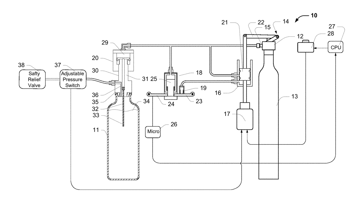
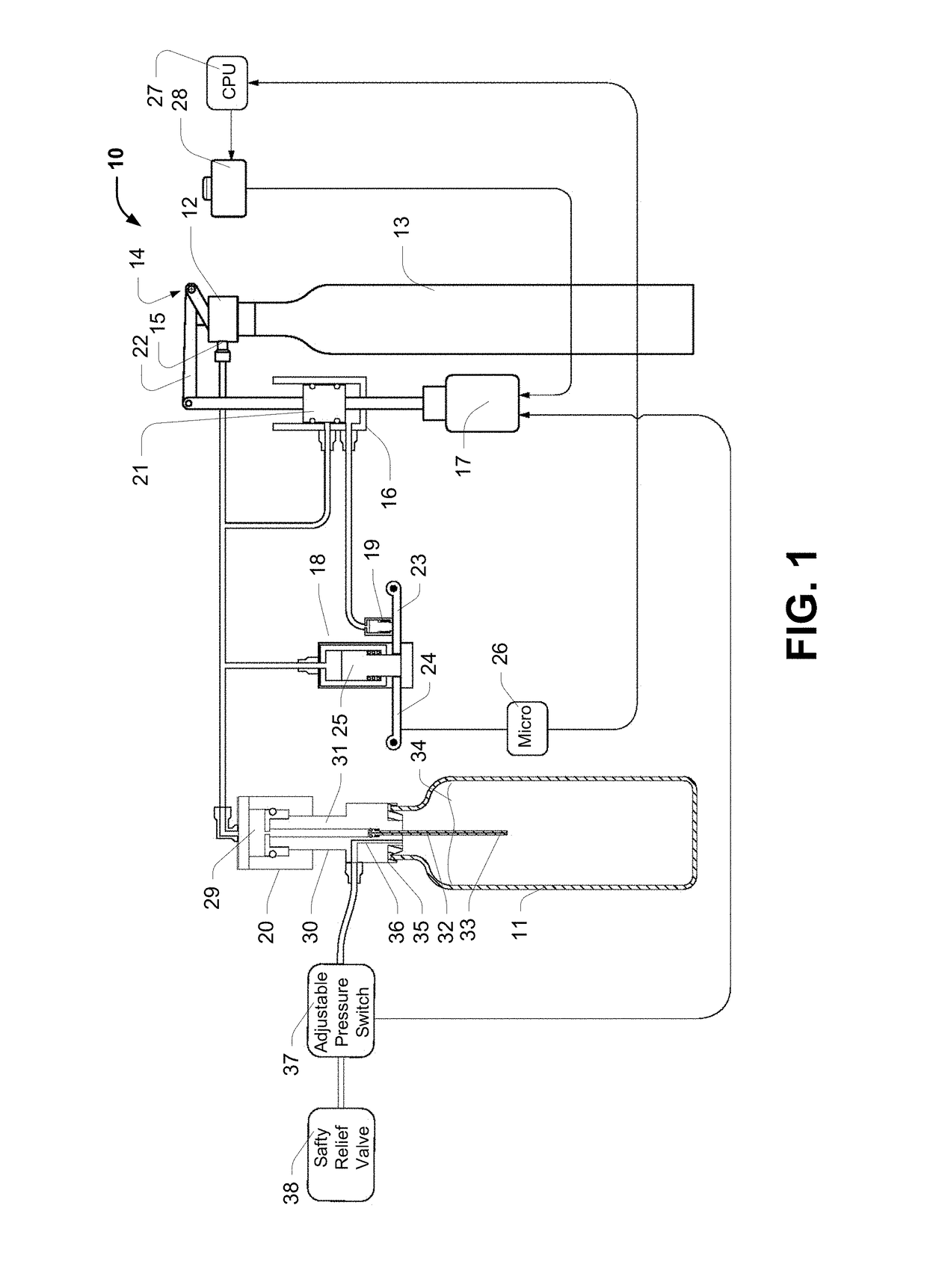
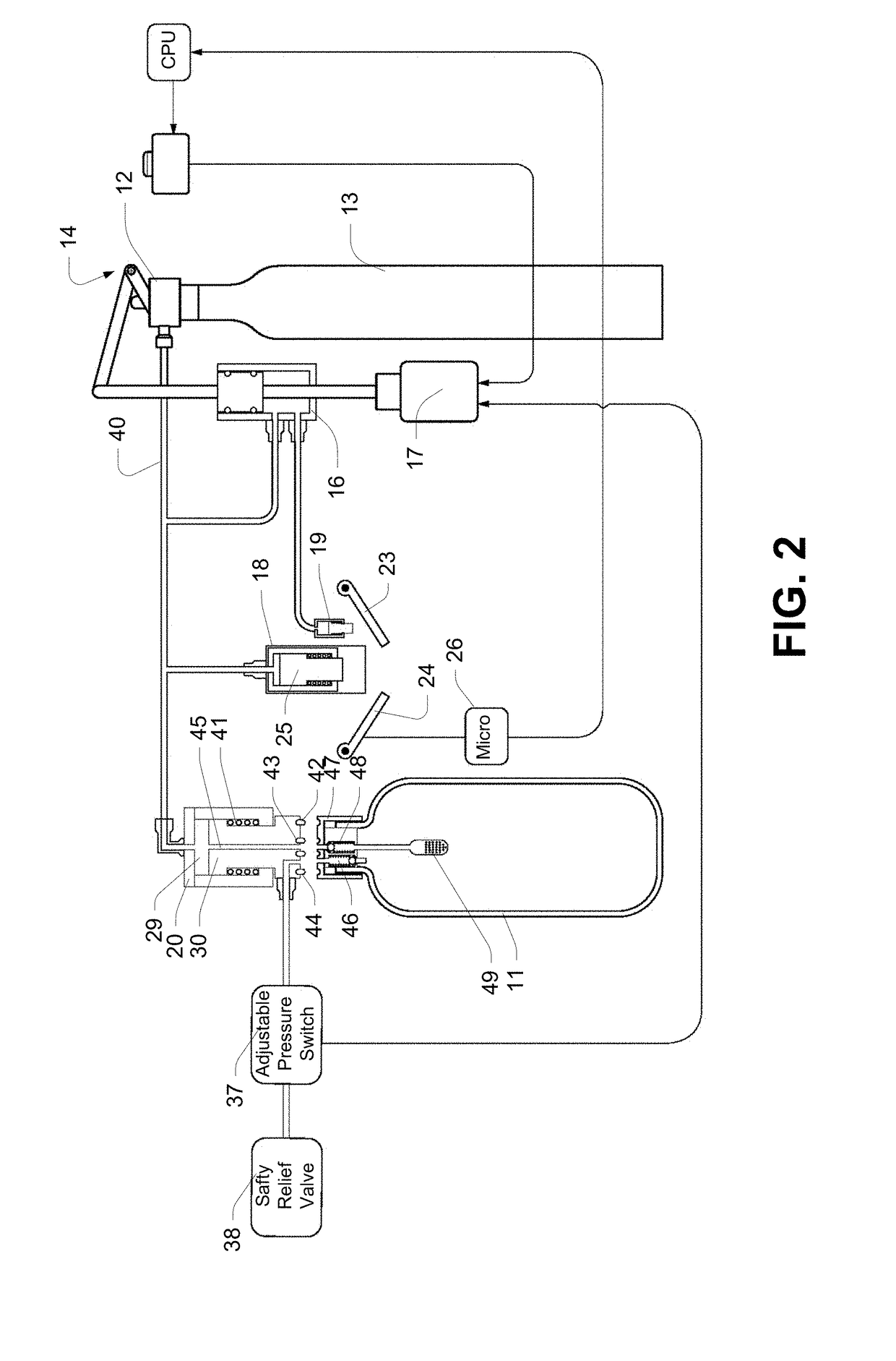
[0046]As shown in FIG. 1, a device to for force carbonating the liquid in a bottle with no thread or bayonet fitting to connect it with a fill head. The device has a primary dispensing coupling or valve 12 that is adapted to receive an interchangeable carbon dioxide (CO2) cylinder 13. The valve 12 includes an activation assembly 14 and an outlet 15. The outlet supplies CO2 to components required by the carbonator 10, through a network of suitable piping or tubing. CO2 from the cylinder 13 is supplied to a diverter valve 16 that is activated by (for example) a solenoid 17. CO2 is also selectively routed to a locking assembly 18, a door opening apparatus 19 and bottle fill head assembly 20.

[0047]As shown in FIG. 1, the solenoid 17 and diverter 16 are shown in a “fill” orientation. In this orientation, a piston 21 in the diverter allows pressurised CO2 flows through to those locations where pressurised CO2 is required but not to the door opening mechanism 19. A mechanical linkage 22 fr...


PUM

PropertyMeasurementUnit
weightaaaaaaaaaa
pressureaaaaaaaaaa
heightaaaaaaaaaa

Abstract

A domestic carbonation appliance. The appliance has a replaceable CO2 cylinder, and accepts a refillable bottle. The appliance has a processor for controlling the functions of the device. The appliance comprises: a chassis having a filling chamber; a fill head in the filling chamber, the fill head being attachable to a source of pressurised carbon dioxide gas; the filling chamber having a safety door and locking device; the device having a sensor for detecting a door state and transmitting door state information to the processor; and the processor being adapted to initiate a carbonation process in response to the door state information.

Description

FIELD OF THE INVENTION[0001]The invention pertains to carbonation devices and more particularly to carbonation devices for domestic use.BACKGROUND OF THE INVENTION[0002]Domestic carbonators are well known. These devices operate by injecting pressurised carbon dioxide into a liquid that is contained in a sealed bottle. The present invention aims to improve known devices and methods by simplifying and automating aspects of the carbonation process and by providing additional sophistication in the construction of the device and the bottles that are used during the carbonation process.[0003]Known domestic carbonation devices require a threaded or bayonet coupling assembly between the bottle to be carbonated and the carbonation head prior to starting the carbonation process. These types of coupling arrangements generally require two hands. In some prior art units that do not have water delivery, the bottle is being handled while full, making the coupling procedure more difficult owing to ...

Claims


Application Information

Patent Timeline
Patent Type & Authority Applications(United States)
IPC IPC(8): B01F3/04B01F13/04A23L2/54B01F35/60
CPCA23L2/54B01F3/04794B01F13/042B01F13/047B01F15/00155B01F15/00162B01F15/00253G01F17/00G01F13/00G01F22/02B01F23/2361B01F35/602B01F35/6052B01F35/2113B01F35/2112B01F35/2209
Inventor MCCLEAN, STEPHEN JOHNGRIGOR, ANDREW
Owner BREVILLE HLDG PTY LTD
Learn More