Automatic injection devices

a technology of injection device and injection needle, which is applied in the field of injection device, can solve the problems of increasing manufacturing cost, increasing device complexity, and less intuitive use of the device by the end user

Inactive Publication Date: 2017-08-31
OWEN MUMFORD
View PDF0 Cites 12 Cited by
  • Summary
  • Abstract
  • Description
  • Claims
  • Application Information

AI Technical Summary

Benefits of technology

The patent text describes a device for releasing a drive mechanism in an injector device. The device includes a latch that can be expanded radially outward to release the drive mechanism. The device also includes a trigger that prevents the latch from expanding before it is ready to use. The trigger can only be moved forward and cannot return to its original position. The trigger engages with a feature of the latch, allowing the device to be assembled and reducing unintended emissions from the device. The latch has a texture on its rearward face to provide a comfortable and secure feel during use. Overall, this device simplifies assembly and reduces noise during use.

Problems solved by technology

However, such arrangements may result in increased complexity of the device.
Increased complexity may for example result in less intuitive use of the device for the end user.
Further increased complexity may increase manufacturing costs, by increasing part count and / or increasing assembly complexity, which may be particularly disadvantageous for disposable injection devices.

Method used


Image

  • Automatic injection devices
  • Automatic injection devices
  • Automatic injection devices

Examples


Embodiment Construction

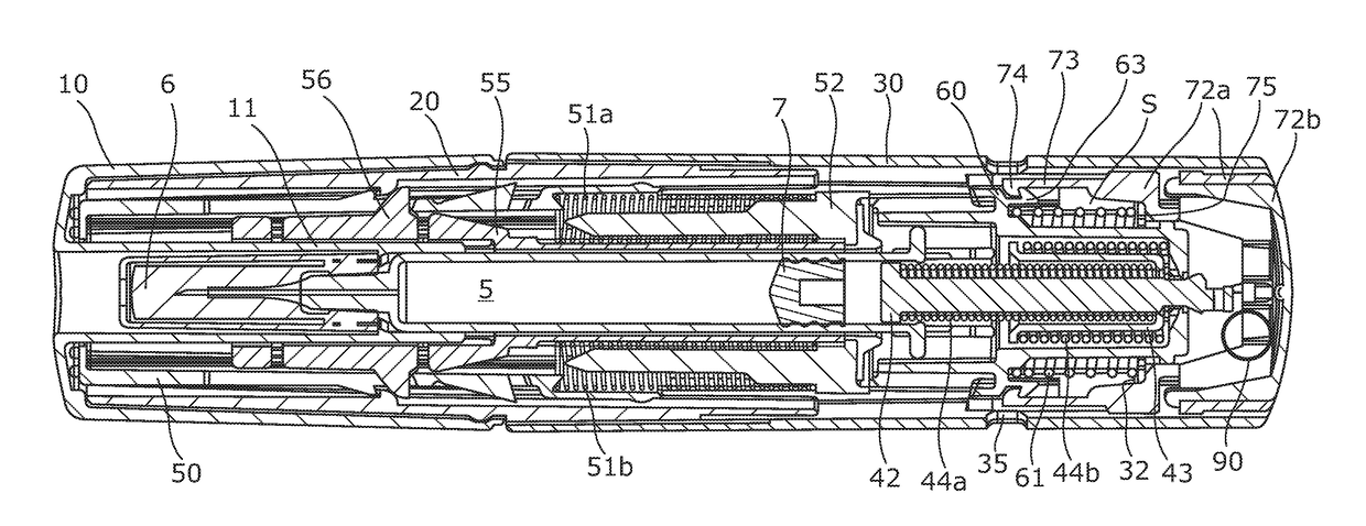
[0094]Front as used herein will be understood to refer to the end of the injector assembly (or components thereof) which, in use, are closest to the delivery needle delivery end of the injector (i.e. the end which is pointed at the skin). Rear as used herein will be understood to refer to the end of the pen injector assembly (or components thereof) which, in use, are furthest from the needle delivery end of the injector (i.e. the end which is pointed away from the skin). Forward and rearward will, likewise, be understood to refer to the directions orientated towards the front and rear of the injector assembly.

[0095]Axial, radial and circumferential are used herein to conveniently refer to the general directions relative to the longitudinal direction of the injection device (or components thereof). The skilled person will, however, appreciated that these terms are not intended to be narrowly interpreted (and for example, the injection device may have a non-circular and / or irregular f...


PUM


Abstract

An injection device for delivering a dose of medicament from a syringe includes: a housing including a forward body and rearward body and wherein the forward and rearward body are axially moveably interconnected; a drive mechanism arranged, in use, to be released from an energized position to deliver a dose from the syringe; a latch arranged to hold the drive mechanism in the energized position; and a trigger for releasing the latch; wherein the injection device further includes an interlock arrangement moveable between a locked position in which release of the drive mechanism is prevented and an unlocked position in which the drive mechanism may be released, the interlock arrangement including: an internal blocking formation associated with the rearward body and positioned between the latch and trigger, and wherein in use, forward movement of the rearward body relative to the forward body moves the blocking formation into the unlocked position.

Description

FIELD OF THE INVENTION[0001]This invention relates to injection devices for delivering a dose of medicament from a syringe. In particular, but not exclusively the invention relates to an “autoinjector” device.BACKGROUND OF THE INVENTION[0002]Injection devices are used for the convenient administration of medicaments. For example, injection devices (which may typically be in the form of a pen injector) may be used for providing a single metered dose of a medicament, such as Epinephrine, in an emergency or for providing regular metered doses of a medicament, such as Insulin. Such devices may be either single use “disposable” devices in which the device is typically provided with a syringe already installed, and which is not user-replaceable, or “reusable” devices which allow the user to replace the syringe when the medicament has been used.[0003]It may be noted that whilst the term “syringe” is used herein for clarity and consistency, however the skilled person will appreciate that th...

Claims


Application Information

Patent Timeline
Patent Type & Authority Applications(United States)
IPC IPC(8): A61M5/32A61M5/315A61M5/50A61M5/20
CPCA61M5/3257A61M5/2033A61M5/3202A61M5/31511A61M2005/208A61M2005/2013A61M2005/206A61M2005/2073A61M5/5086A61M5/3204
Inventor COWE, TOBYFARMER, MATTHEWMULLER, TIM
Owner OWEN MUMFORD
Why Eureka
Try Eureka