
Process for the return extrusion of internal profiles

A technology of inner profile and process, which is applied in the field of inner profile, can solve the problems of incomplete filling and unusability of the profile

Active Publication Date: 2007-01-31
GKN DRIVELINE INT GMBH
View PDF0 Cites 0 Cited by
  • Summary
  • Abstract
  • Description
  • Claims
  • Application Information

AI Technical Summary

Problems solved by technology

[0003] When carrying out said prior art process, there are limitations with regard to the height of the profile, i.e. the difference between the minimum and maximum cross-section of the forming die
Surface filling becomes incomplete as deformation increases
The material no longer completely fills the tool profile of the forming die, resulting in an unusable product

Method used


Image

  • Process for the return extrusion of internal profiles
  • Process for the return extrusion of internal profiles
  • Process for the return extrusion of internal profiles

Examples


Embodiment Construction

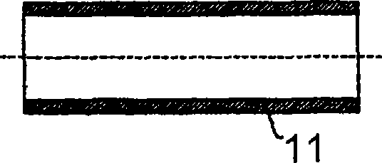
[0021] figure 1 The details of a tube 11 are shown, in which an inner profile is about to be produced. It is also possible to use a substantially uniform closed tubular profile instead of the tube. In this case, the support sleeve and the forming die must be adapted accordingly.

[0022] In FIG. 2, the tube 11 is inserted into a support sleeve 12 in a substantially gap-free manner, and in order to obtain axial support, the two are located on a base plate 13 with a central hole. The base plate 13 directly supports the first tube end 19. The second rear tube end 20 is the free end. At a distance from the support sleeve 12, a coaxially arranged mold 14 with an attached molding mold 15 is provided in order to create an inner profile in the tube 11. On the mold 14, an annular mold 16 is slid, and at its front end, there is an inner groove 17 partially accommodating the molding mold 15.

[0023] In FIG. 3, the forming mold 15 for producing an inner profile 18 has been partially presse...


PUM


Abstract

The invention relates to the production of an internal profile (18) in a pipe or hollow profile. Said method consists of inserting the pipe or hollow profile (11) into a supporting sleeve (12) by axially supporting one first end of the pipe (19); placing a pressure-loaded annular stamp (16) onto the other end of the pipe (20); pressing a form stamp (15), comprising an external profile, into the pipe or hollow profile (11) from the other end of the pipe (20) in order to produce the inner profile (18); releasing the annular stamp (16) by the pressure load in the direction counter to that of pressing in the form stamp (15).

Description

Invention field [0001] The invention relates to a process for producing an inner profile in a tube or hollow profile. Background technique [0002] According to this process, the tube or hollow profile has a substantially uniform wall thickness before being deformed, and is placed in a suitable support sleeve, starting from a tube end, by pressing in a forming die, When deformed, the outer surface of the molding die corresponds to the inner surface to be produced. As a result of the outer surface of the forming die, the displaced material results in the reverse extrusion of the deformed tube or profile at the end of the tube in the support sleeve. [0003] When implementing the prior art process, there are restrictions on the height of the profile, that is, the restriction on the difference between the minimum cross section and the maximum cross section of the molding die. As the degree of deformation increases, the filling of the profile becomes incomplete. The material no longe...

Claims


Application Information

Patent Timeline
Patent Type & Authority Applications(China)
IPC IPC(8): B21C23/20B21K1/76B21K1/12B21C37/20B21J5/12
CPCB21C23/20B21J5/12B21C37/202B21K1/12B21K1/762B21K1/066
Inventor U·布洛切瑟A·格哈克
Owner GKN DRIVELINE INT GMBH
Learn More