
Aerosol-generating systems with liquid level determination and methods of determining liquid level in aerosol-generating systems

a technology of aerosol-generating systems and liquid level determination, which is applied in the direction of liquid/fluent solid measurement, tobacco, instruments, etc., can solve the problems of liquid level only being determined, liquid depletion only being determined

Active Publication Date: 2017-08-31
AKRIA CLIENT SERVICES LLC
View PDF5 Cites 62 Cited by
  • Summary
  • Abstract
  • Description
  • Claims
  • Application Information

AI Technical Summary

Benefits of technology

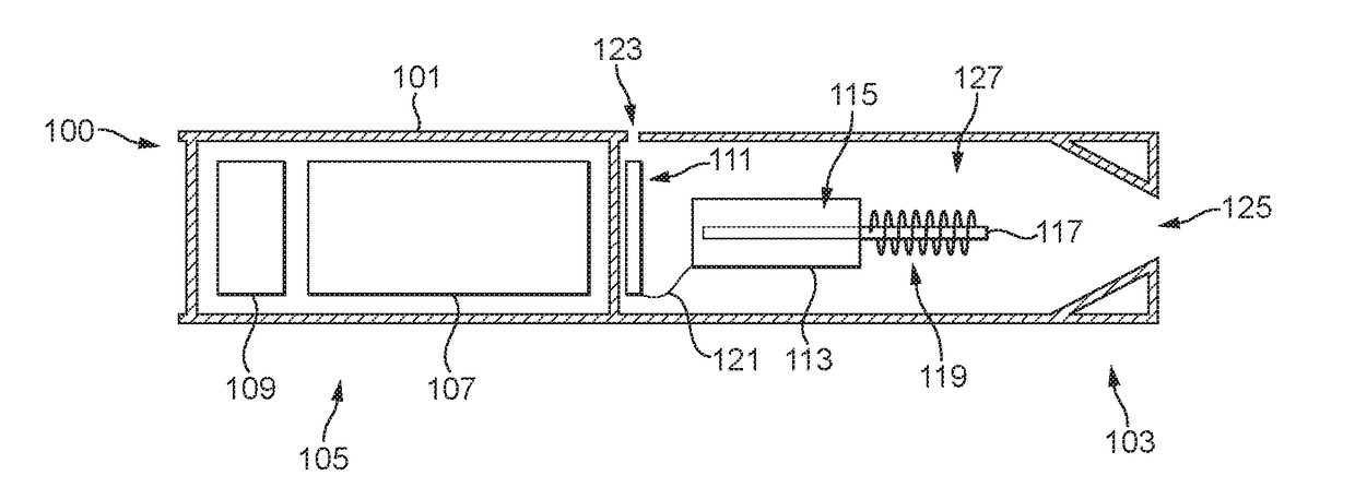
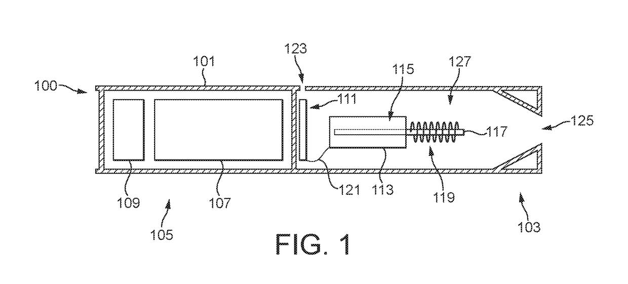
The patent describes an electrically operated aerosol-generating system that includes a liquid storage portion, an electric heater, a capillary wick, and electric circuitry. The system uses a temperature measurement of the electric heater during a cooling time period after a heating time period to determine the amount of liquid in the system. The system can activate the electric heater for a second heating time period after a first cooling time period. The method and computer program allow for accurate detection of liquid levels in the system and efficient control of the electric heater.

Problems solved by technology

This means that liquid depletion can only be determined when the level of liquid in the liquid storage portion has been significantly depleted.
It also means that liquid level can only be determined as air is being drawn through the outlet.

Method used


Image

  • Aerosol-generating systems with liquid level determination and methods of determining liquid level in  aerosol-generating systems
  • Aerosol-generating systems with liquid level determination and methods of determining liquid level in  aerosol-generating systems
  • Aerosol-generating systems with liquid level determination and methods of determining liquid level in  aerosol-generating systems

Examples


first embodiment

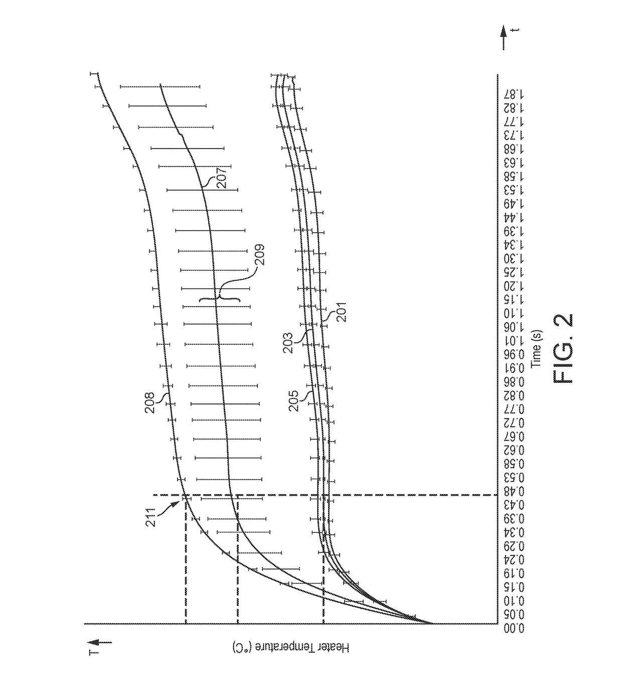
[0120]Liquid level based on wicking rate can be determined in a number of ways. FIG. 5 illustrates a control process configured to determine liquid level by determining wicking rate based on a single heater activation. The process of FIG. 5 relies on an assumption that following a heater activation to vaporize liquid in the wick, the level of liquid in the vicinity of the wick is consistent. So a measure of liquid level immediately after an activation of the heater is not measured but has been determined during a calibration process during manufacture or device development.

[0121]FIG. 5 illustrates the activation of the heater over time. In FIG. 5 power is applied to the heater in response to air being drawn through the system and through the outlet (referred to herein as an “air draw” and / or “draw of air”), as illustrated by vaporizing period 500. The application of power to the heater in response to the air draw being ended at time t0. At time t0 the liquid in the wick is depleted ...

second embodiment

[0123]FIG. 6 is a control process configured to determine liquid level based on two heater activations. In FIG. 6 power is applied to the heater in response to air being drawn through the system and through the outlet thereof, as illustrated by vaporizing period 600. The application of power to the heater in response to the draw of air being ended at time t0. At time t0 the liquid in the wick is depleted as a result of vaporization. At time t1, which is a set period after to, power is applied to the heater again for a second period 610. The second period 610 is shorter than the vaporizing period 600 and is sufficiently short that the heater does not reach the vaporization temperature of the liquid. At time t2, which is at or close to the end of the second period 610, the temperature of the heater is measured. At time t3, which is a set period after to, power is applied to the heater again for a third period 620. The third period 620 is also shorter than the vaporizing period 600 and...


PUM


Abstract

An electrically operated aerosol-generating system may include a liquid storage portion configured to store a liquid from which aerosol may be generated, an electric heater, a capillary wick extending between the liquid storage portion and the electric heater and configured to convey liquid from the liquid storage portion to the electric heater and electric circuitry connected to the electric heater. The electric circuitry may be configured to: activate the electric heater for a first heating time period in response to an input to vaporize liquid in the capillary wick, activate the electric heater for a second heating time period upon the elapse of a first cooling time period after the first heating time period, record a temperature measurement of the electric heater during the second heating time period, and determine an amount of liquid in the liquid storage portion based on the temperature measurement.

Description

CROSS-REFERENCE TO RELATED APPLICATIONS[0001]This application is a continuation of, and claims priority to, international application no. PCT / EP2017 / 050374, filed on Jan. 10, 2017, and further claims priority under 35 U.S.C. §119 to European Patent Application No. 16157420.7, filed Feb. 25, 2016, the entire contents of each of which are incorporated herein by reference.BACKGROUND[0002]Field[0003]Some example embodiments relate to an electrically operated aerosol-generating system. In particular, some example embodiments relate to an electrically operated aerosol-generating system in which an aerosol-forming substrate is liquid and is contained in a liquid storage portion.[0004]Description of Related Art[0005]WO 2012 / 085203 A1 discloses an electrically heated vaping system having a liquid storage portion. The liquid storage portion includes a liquid aerosol-forming substrate and is connected to a vaporizer comprising an electric heater which is powered by a battery supply. The electr...

Claims


Application Information

Patent Timeline
Patent Type & Authority Applications(United States)
IPC IPC(8): A24F47/00G01F23/22H05B1/02A24F40/10A24F40/50
CPCA24F47/008G01F23/22H05B1/0244G01F22/00H05B1/0227A24F40/10A24F40/50
Inventor REEVELL, TONY
Owner AKRIA CLIENT SERVICES LLC
Learn More