Circuit breaker with quick response and separation and quick response and separation method for circuit breaker

Inactive Publication Date: 2017-08-10
TECH POWER INT
View PDF3 Cites 0 Cited by
  • Summary
  • Abstract
  • Description
  • Claims
  • Application Information

AI Technical Summary

Benefits of technology

The present invention provides a circuit breaker with the following technical benefits: quick opening, flexible and any-time breaking, simple structure. The breakage contact replaces a fixed contact in the conventional art, allowing for quick separation between contacts due to a two-way separation action. This avoids or reduces electric arc phenomenon, prolongs the service life of the circuit breaker. The breaking contact can move independently of the joint contact, making the circuit breaker safer. The insulating plate structure and contact compression springs ensure better insulating and arc extinction effects. Different switch structures are provided for pivoted shaft, enhancing the design options. The quick response and separation method of the circuit breaker ensures quick separation between contacts, reducing the electric arc phenomenon and prolonging service life. The breaking contact and joint contact move in opposite directions prior to separation, further reducing the electric arc phenomenon. The circuit breaker is safer as the breaking contact can move independently of the joint contact.

Problems solved by technology

When the circuit needs to be broken, the speed of separating the fixed contact from the joint contact is slow since only one movable joint contact is moved.
Consequently, the contacts are damaged, and the service life of the circuit breaker is shortened.
(2) The breaking control is not flexible, and a breaking operation cannot be performed at any time.
Particularly, when the joint contact is being closed or has just been closed, the breaking operation cannot be performed at any time, and there is a potential safety hazard.
(3) The structure is complicated.
In the prior art, in order to eliminate the electric arc phenomenon, various arc extinction apparatuses or devices usually need to be additionally provided, so the structure design is complicated and the cost of the circuit breaker increases.

Method used


Image

  • Circuit breaker with quick response and separation and quick response and separation method for circuit breaker
  • Circuit breaker with quick response and separation and quick response and separation method for circuit breaker
  • Circuit breaker with quick response and separation and quick response and separation method for circuit breaker

Examples


first embodiment

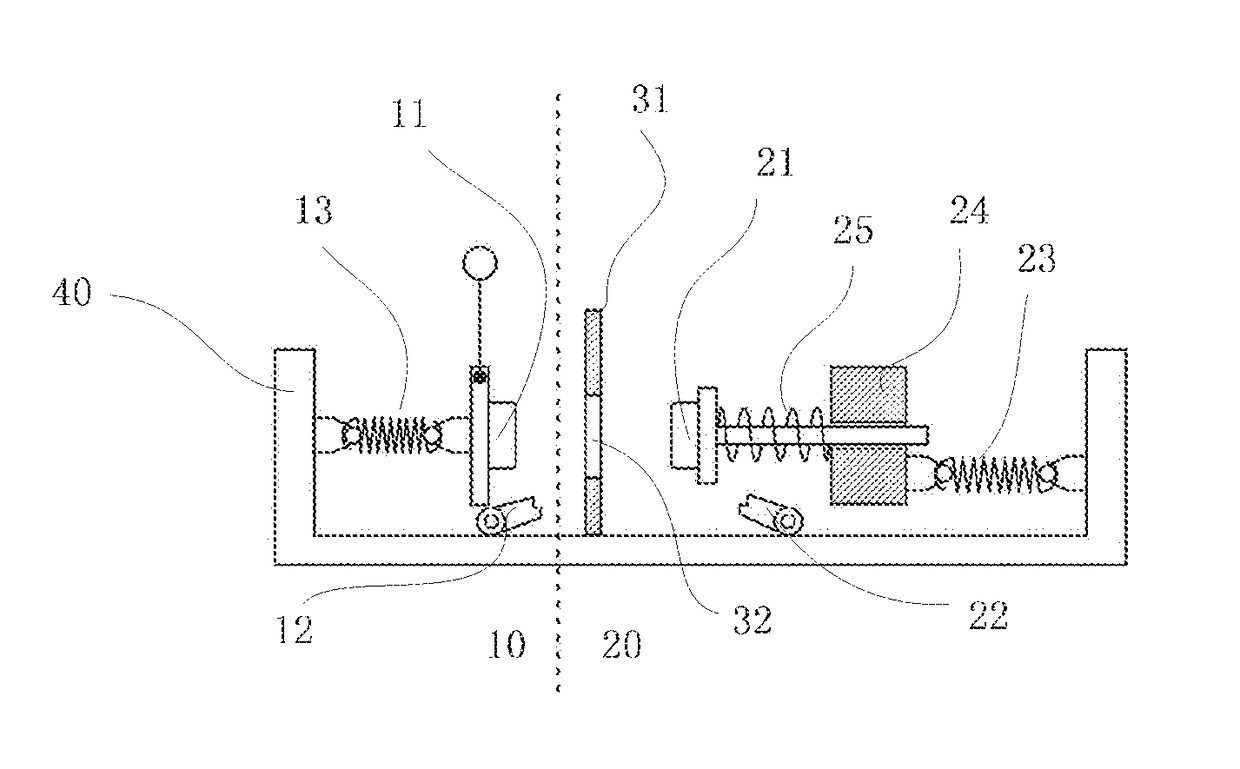
[0048]As shown in FIG. 1, in the present invention, the circuit breaker has a pedestal 40; both the breaking contact lock catch 12 and the joint contact lock catch 22 are arranged on the pedestal 40; one end of the breaking separation spring 13 is fixed on the pedestal 40, while the other end thereof is connected to the breaking contact; and, the extension and contraction of the breaking separation spring 13 and the extension and contraction of the joint contact spring drives the breaking contact 11 and the joint contact 21 to move in a same straight line direction, respectively. The joint contact group 20 further includes a joint contact thrust plate 24 and a contact compression spring 25, and the joint contact 21 is connected to one end of the joint contact separation spring 23 successively through the contact compression spring 25 and the joint contact thrust plate 24. The movable contact limiting device is a contact baffle 31, and a through hole 32 for allowing the breaking cont...

second embodiment

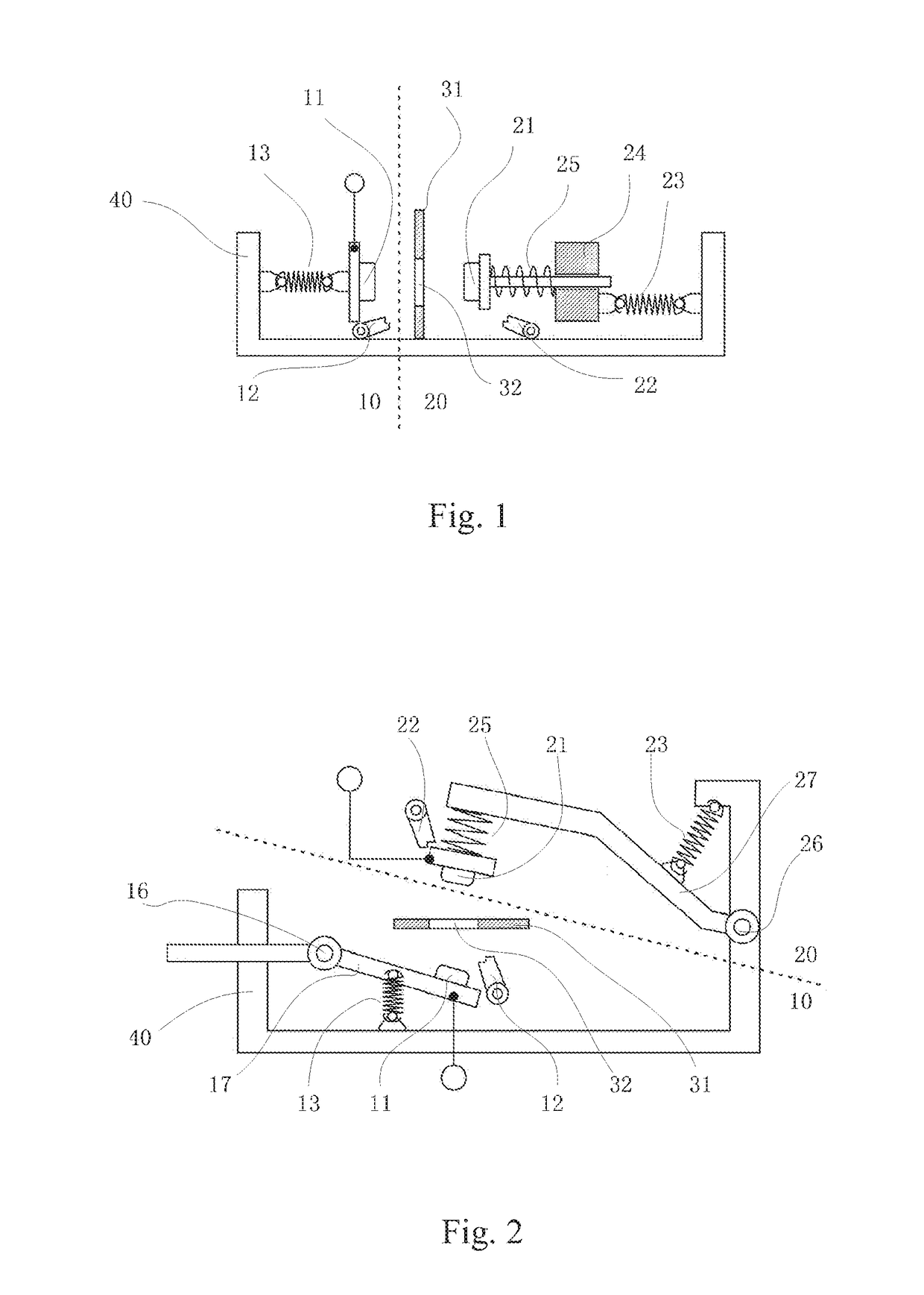
[0065]As shown in FIG. 2, in the present invention, the breaking joint group 10 further includes a breaking pivoted shaft 16 and a breaking pivoted arm 17, and the breaking separation spring 13 drives the breaking contact 11 to swing around the breaking pivoted shaft 16 through the breaking pivoted arm 17. The joint contact group 20 further includes a joint pivoted shaft 26 and a joint pivoted arm 27, and the joint contact separation spring 23 drives the joint contact 21 to swing around the joint pivoted shaft 26 through the joint pivoted arm 27. Preferably, the joint contact group 20 further includes a joint contact thrust plate 24 and a contact compression spring 25, and the joint contact 21 is connected to one end of the joint contact separation spring 23 successively through the contact compression spring 25, the joint contact thrust plate 24 and the joint pivoted arm 24.

[0066]As shown in FIG. 7, the working process S201 to S212 of the second embodiment of the present invention ...

fourth embodiment

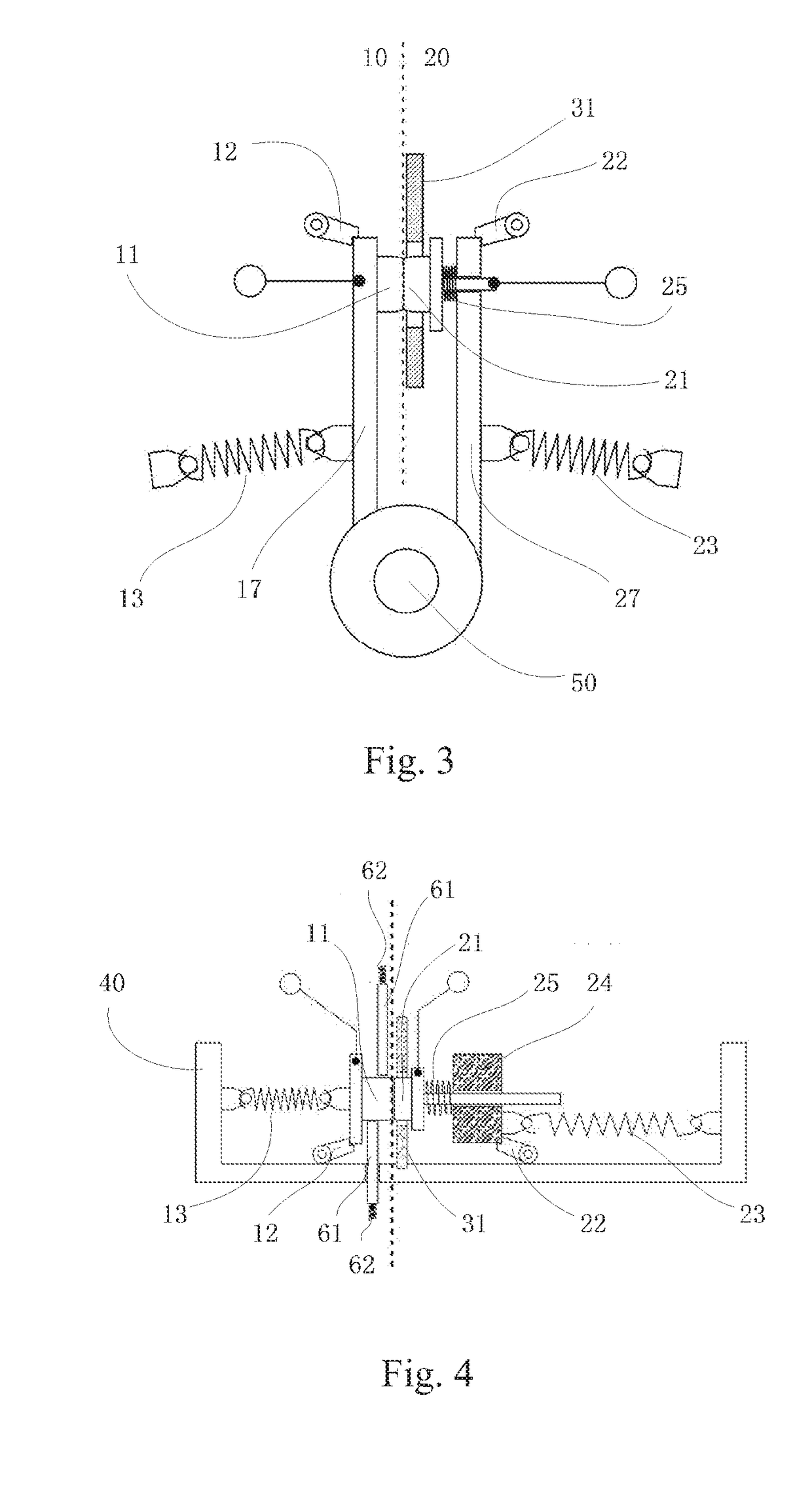
[0068]As shown in FIG. 4 or FIG. 9, in the present invention, the circuit breaker further includes one or more insulating plates 61. When the breaking contact 11 is separated from the joint contact 21, the insulating plates 61 are inserted between the breaking contact 11 and the joint contact 21, and the insulating plates 61 are connected to an insulating plate spring 62 for providing to the insulating plates 61 a driving force for insertion. In the present invention, the insulating plate 61 structure is additionally arranged between the breaking contact 11 and the joint contact 21, so better insulating and arc extinction effects are realized while quickening the opening speed of the circuit breaker.


PUM


Abstract

A circuit breaker with quick response and separation and a quick response and separation method for the circuit breaker. The circuit breaker comprises a breaking contact group and a joint contact group. The breaking contact group comprises a movable breaking contact. The joint contact group comprises a movable joint contact. A movable contact limiting device used for limiting moving positions of the breaking contact and / or the joint contact is arranged between the breaking contact group and the joint contact group. The quick response and separation method for the circuit breaker comprises a breaking and opening step, wherein the breaking contact moves in a reverse direction and is separated independently ahead of the joint contact, or the breaking contact and the joint contact both move in a reverse direction and are separated at the same time.

Description

FIELD OF THE INVENTION[0001]The present invention relates to power control equipment and in particular to a circuit breaker and a quick response and separation method for the same.BACKGROUND OF THE INVENTION[0002]A circuit breaker is a switch device which can close, load and break the current in a normal circuit, and close, load within a scheduled time and break the current in an abnormal circuit.[0003]At present, various circuit breakers have been widely applied in real life. In the conventional art, a circuit breaker generally includes a fixed contact at a fixed position and a movable joint contact, wherein the joint contact is moved to break the circuit connection in an abnormal circuit. In the prior art, circuit breakers have the following deficiencies.[0004](1) The separation speed is slow. When the circuit needs to be broken, the speed of separating the fixed contact from the joint contact is slow since only one movable joint contact is moved. Particularly, as the contact with...

Claims


Application Information

Patent Timeline
IPC IPC(8): H01H71/10H01H71/24H01H71/12
CPCH01H71/10H01H2235/01H01H71/24H01H71/128H01H73/04H01H73/18H01H1/64H01H3/0253H01H9/32
Inventor TO, MANFUKHO, KENNY
Owner TECH POWER INT
Why Eureka
Try Eureka