
Recovery point objectives in replication envrionments

a recovery point and replication technology, applied in data switching networks, fault response, instruments, etc., can solve problems such as replication lag, failure to allow end users to change software, and breach of one or more service level agreements (slas), so as to increase the input/output bandwidth and increase the network bandwidth

Active Publication Date: 2017-08-03
VERITAS TECH
View PDF7 Cites 10 Cited by
  • Summary
  • Abstract
  • Description
  • Claims
  • Application Information

AI Technical Summary

Benefits of technology

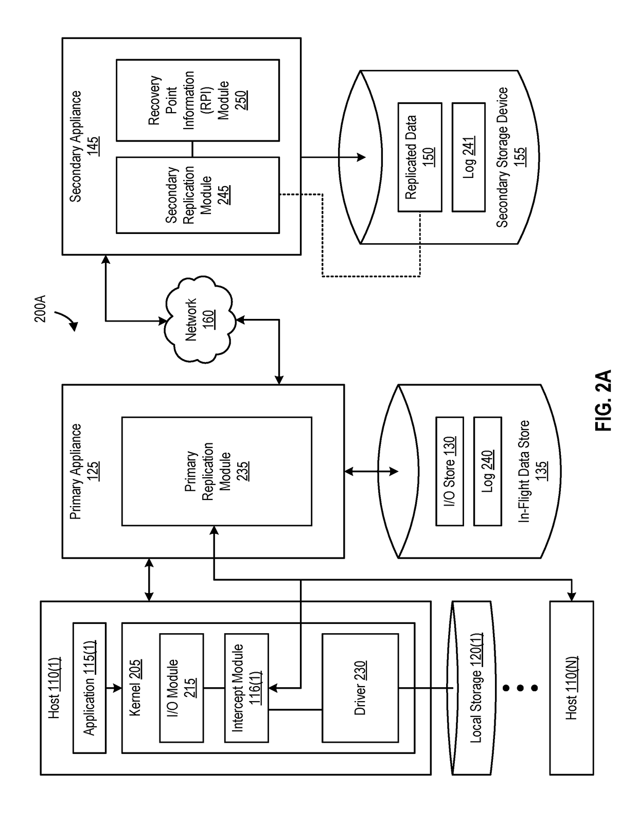
The patent describes methods, systems, and processes for adjusting replication operations in a distributed environment. This involves receiving a set of replicated data from a first appliance as a result of a replication operation. The method then performs a write operation to store the set of replicated data and records a second timestamp. The second timestamp is used to generate recovery point information that is used to adjust replication parameters for a subsequent replication operation. The recovery point information can be utilized by the first appliance to perform the adjustment. The method can also transmit the recovery point information to the first appliance and update a log in response to the recovery point information. The foregoing is intended to help ensure that the requirements for replicating data are met and the system operates efficiently.

Problems solved by technology

Unlike general purpose computers, appliances are not designed to allow end users to change the software (including the underlying operating system).
Replicating data from the first appliance to the second appliance results in replication lag.
Replication lag associated with replication operations in a distributed environment can result in the breach of one or more Service Level Agreements (SLAs).

Method used


Image

  • Recovery point objectives in replication envrionments
  • Recovery point objectives in replication envrionments
  • Recovery point objectives in replication envrionments

Examples


Embodiment Construction

Introduction

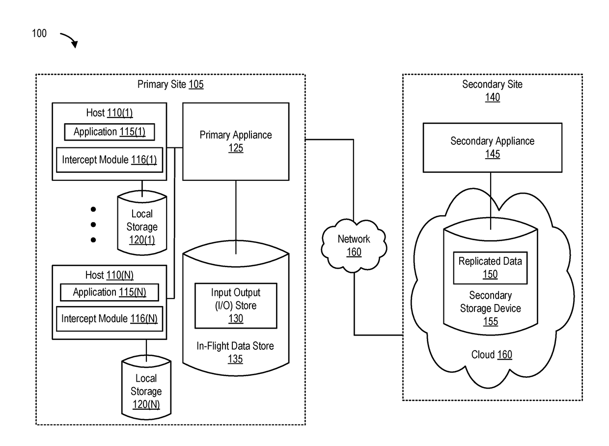
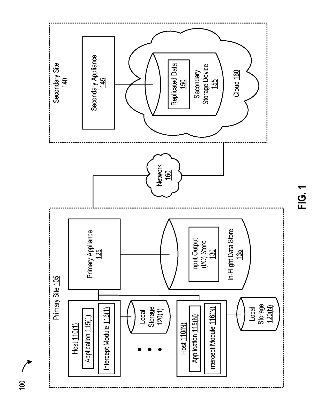
[0028]FIG. 1 is a block diagram of a distributed replication system, according to one embodiment. In this example, such a distributed replication system includes at least two sites—a primary site 105 and a secondary site 140. Primary site 105 and secondary site 140 can be data centers, clusters, cloud environments, and the like. Primary site 105 and secondary site 140 are communicatively coupled to each other via network 160. Network 160 can include any type of network or interconnection (e.g., the Internet, a Wide Area Network (WAN), a Storage Area Network (SAN), and the like).

[0029]Primary site 105 includes hosts 110(1)-(N). Each host execute one (or more) applications and uses a local storage. For example, host 110(1) executes application 115(1) and uses a local storage 120(1). Local storage 120(1) can be used to store I / Os generated by application 115(1). Primary site 105 also implements a primary appliance 125 (e.g., a premise appliance). Primary appliance 125 can b...


PUM


Abstract

Disclosed herein are methods, systems, and processes to adjust replication operations in a distributed environment. A set of replicated data is received from a first appliance as a result of a replication operation. The replication operation is initiated by the first appliance and the set of replicated data includes a first timestamp. A write operation is performed to store the set of replicated data and a second timestamp is recorded. Recovery point information is generated based on the first timestamp and the second timestamp. The recovery point information is configured to be utilized in adjusting replication parameters of a subsequent replication operation.

Description

FIELD OF THE DISCLOSURE[0001]The present disclosure relates to data replication and, more particularly, to adjusting replication operations in a distributed environment.DESCRIPTION OF THE RELATED ART[0002]Appliances can be hardware devices with integrated software or virtual devices (e.g., pre-configured virtual machine images created by installing software appliances on virtual machines). Appliances can be designed and configured to perform replication operations. Unlike general purpose computers, appliances are not designed to allow end users to change the software (including the underlying operating system). In this manner, appliances are designed to be secure black boxes for end users (e.g., customers).[0003]Data replication involves replicating data associated with application input / output (I / O) operations over a network to remote sites, making the replicated data available for processing (e.g., data backup, disaster recovery, data mining, or the like). In certain replication e...

Claims


Application Information

Patent Timeline
IPC IPC(8): G06F11/14H04L12/24G06F17/30
CPCG06F11/1464G06F2201/835H04L41/5019G06F17/30575G06F11/3495G06F11/2069G06F11/2074G06F11/3034G06F11/3419G06F11/3442G06F2201/81G06F16/27
Inventor DOSHI, TUSHARVAIDYA, ANISH A.SHAH, KUSHAL B.
Owner VERITAS TECH
Learn More