Spectacle lens for car drivers
a technology for car drivers and spectacles, applied in the field of spectacle lenses, can solve the problems of glare caused by the headlights of approaching vehicles, streetlights or reflections being extremely irritating, and the driver's glare being glare, etc., and achieve the effect of improving vision
- Summary
- Abstract
- Description
- Claims
- Application Information
AI Technical Summary
Benefits of technology
Problems solved by technology
Method used
Image
Examples
first embodiment
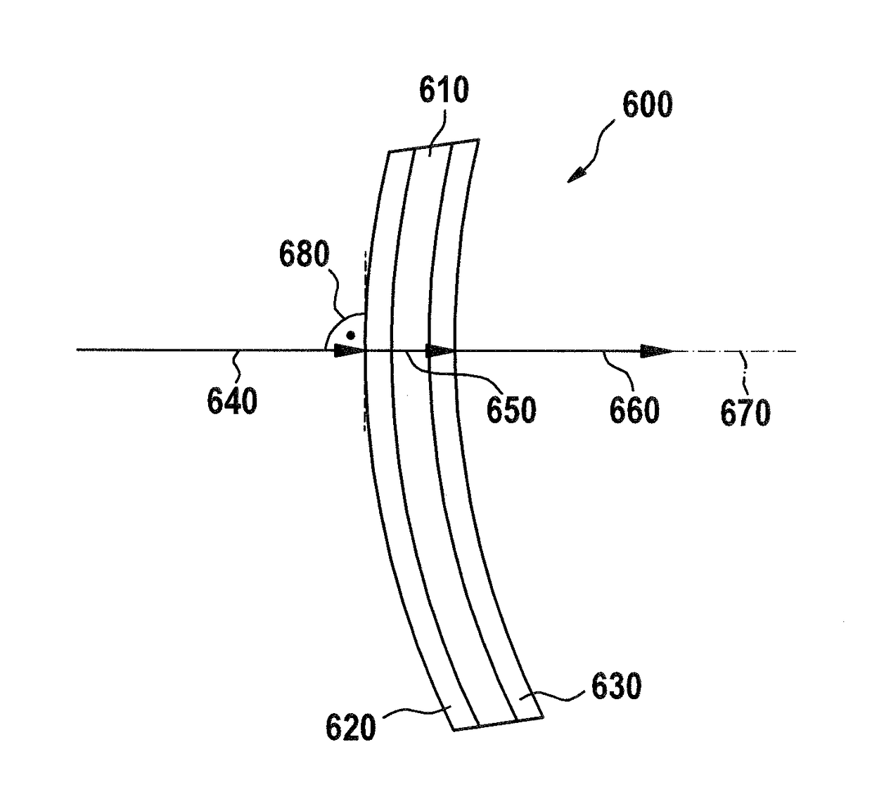
[0094]FIG. 6 shows the cross section of a spectacle lens 600 according to the invention. The spectacle lens 600 shown in a partial section, which is not true to scale, in FIG. 6 has a substrate 610 made of plastic, for example the plastic MR-8. Both sides of the substrate 610 are covered with coatings (620, 630) being described in more detail below.
[0095]FIG. 6 also shows the measurement conditions for determining transmittance and yellowness index. In particular, a light ray 640 enters the spectacle lens at its convex front side, transmits the spectacle lens 600 including coating 620, substrate 610, coating 630 as indicated by arrow 650 and leaves the spectacle lens 600 at its concave back surface before entering a measuring apparatus (not shown) but indicated by the dashed line 670. The light ray 640 enters the front surface at normal incidence 680, for example, 0° (angle of incidence) with respect to the surface normal of the front surface at its entrance point (in general the fa...
second embodiment
[0101]FIG. 7 shows the cross section of a spectacle lens 700 according to the invention. The spectacle lens 700 shown in a partial section, which is not true to scale, in FIG. 7 has a substrate 710 made of plastic, for example the plastic MR-8. Both sides of the substrate 710 are covered with coatings (720, 730).
[0102]While the front side of the substrate 710 is covered with the same coating 620 described above, the back side of the substrate 710 is covered with a different layer structure. The layer structures on top the front side of the substrate and on top of the back side of the substrate are shown in the following Tables 2 and 3, respectively.
TABLE 2Blue attenuating antireflection coating 720 applied tothe front side of the substrate 710 of a spectacle lens700 according to the invention shown in FIG. 7Coating StructureThickness (nm)SubstrateMR8Hard CoatHigh Index Hard Resin3000Pre-etching—AdhesionCr / SiO0.6Layer 1Al2O320.0Layer 2SiO2 / Al2O3200.0Layer 3TiO219.0Layer 4SiO2 / Al2O339...
third embodiment
[0104]FIG. 8 shows the cross section of a spectacle lens 800 according to the invention. The spectacle lens 800 shown in a partial section, which is not true to scale, in FIG. 8 has a substrate 810 made of plastic, for example the plastic polycarbonate. Both sides of the substrate 810 are covered with antireflection coatings (820, 830).
[0105]The substrate 810 does not consist of pure polycarbonate, only, but incorporates two dyes of the company LANXESS Deutschland GmbH being located in Leverkusen, Germany. One of the dyes is sold under the trade name MACROLEX Giallo 6G GRAN (as indicated in the SCHEDA DATI DI SICUREZZA No. 06653898 / 2.04, Data di edizione: Sep. 1, 2015), the other one of the dyes is sold under the trade name MACROLEX GIALLO 3G GRAN (as indicated in the SCHEDA DATI DI SICUREZZA No. 56378921 / 2.03, Data di edizione : Nov. 29, 2011). The latter one contains according to the data sheet pyrazolono-colorante-preparato contiene C.I. Solvent Yellow 93. The first one contains ...
PUM
 Abstract
Description
Claims
Application Information
 - R&D
- Intellectual Property
- Life Sciences
- Materials
- Tech Scout
- Unparalleled Data Quality
- Higher Quality Content
- 60% Fewer Hallucinations
Browse by: Latest US Patents, China's latest patents, Technical Efficacy Thesaurus, Application Domain, Technology Topic, Popular Technical Reports.
© 2025 PatSnap. All rights reserved.Legal|Privacy policy|Modern Slavery Act Transparency Statement|Sitemap|About US| Contact US: help@patsnap.com


