
Self-annealing concrete, self-annealing concrete forms, temperature monitoring system for self-annealing concrete forms and method of making and using same

a self-annealing, concrete technology, applied in the direction of forms/shuttering/falseworks, walls, forms/shuttering/falseworks, etc., can solve the problems of cracking of concrete temperature shrinkage, concrete is continuously lost to the environment, and the conventional removable concrete forms do not provide insulation to the concrete wall. , to achieve the effect of improving the curing environment of concr

Active Publication Date: 2017-08-03
CIUPERCA ROMEO ILARIAN
View PDF2 Cites 50 Cited by
  • Summary
  • Abstract
  • Description
  • Claims
  • Application Information

AI Technical Summary

Benefits of technology

The invention relates to a system for insulating concrete forms, which helps to retain heat of hydration within the forms to improve the physical properties of the concrete. By using the insulating panel described in the invention, temperature fluctuations from the concrete surface are significantly reduced, resulting in a more stable and durable concrete structure. The invention also provides an improved curing environment for concrete. The use of the insulating panel in conjunction with a conventional removable concrete form allows for the removal of the form at the usual point in time, leaving behind the insulating panel inserts attached to the concrete until such time as the concrete has achieved the desired temperature curing profile, strength and physical properties.

Problems solved by technology

However, conventional removable concrete forms do not provide insulation to the concrete wall, either during concrete curing or after removal.
Consequently, as the concrete is setting and the hydration process is beginning the concrete internal temperature rises to a first peak temperature while at the same time heat is continuously lost to the environment through the un-insulated concrete form panels.
This rapid cooling creates temperature shock and leads to thermal shrinkage that causes what the industry refers to as concrete temperature shrinkage cracking.
Through the cracks, moisture and salt prematurely reach steel reinforcement which cause corrosion.
Over time, this is a leading cause of concrete failure.
However, such insulated blankets are relatively thin and are not designed or effective to retain the heat of hydration within the concrete formwork.
Although insulated blankets are sometimes used to wrap the concrete after the forms have been removed, such practice is inefficient and doubles cost of installation.
While insulated blankets are sometimes used to wrap mass concrete, the amount of insulation provided by such insulated blankets is relatively low and is only provided to reduce the temperature differential between the surface and the core.
However, for certain applications it may not be desirable to have insulation permanently attached to the concrete.
Furthermore, leaving the insulation permanently attached to the concrete is more expensive than using conventional removable concrete forms.
In the prior art, both the processor / transmitter portion and the temperature sensor portion are embedded in the cured concrete, and, therefore, cannot be reused.
This makes monitoring the temperature of curing concrete relatively costly.

Method used


Image

  • Self-annealing concrete, self-annealing concrete forms, temperature monitoring system for self-annealing concrete forms and method of making and using same
  • Self-annealing concrete, self-annealing concrete forms, temperature monitoring system for self-annealing concrete forms and method of making and using same
  • Self-annealing concrete, self-annealing concrete forms, temperature monitoring system for self-annealing concrete forms and method of making and using same

Examples


Embodiment Construction

[0055]U.S. Pat. Nos. 8,545,749; 8,636,941 and 9,458,637 and are all incorporated herein by reference in their entirety.

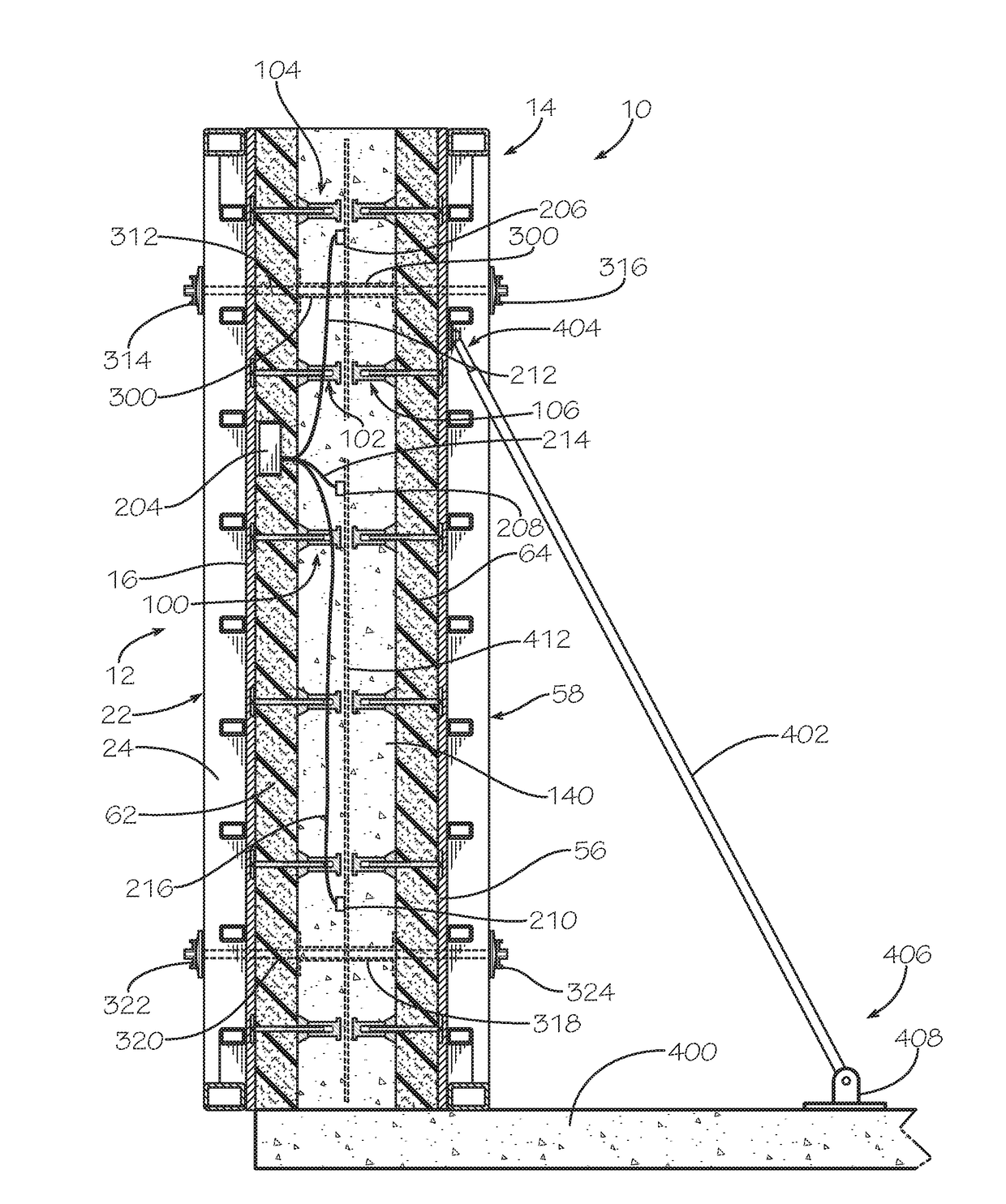
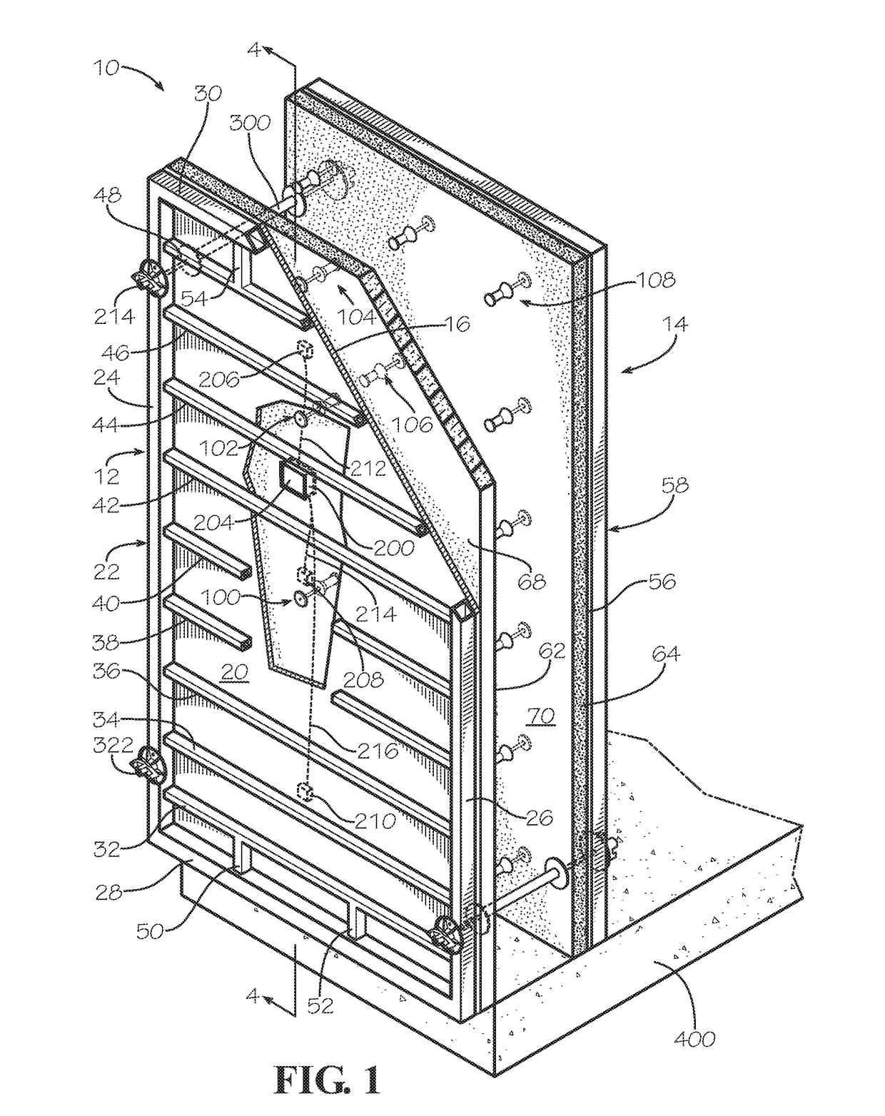
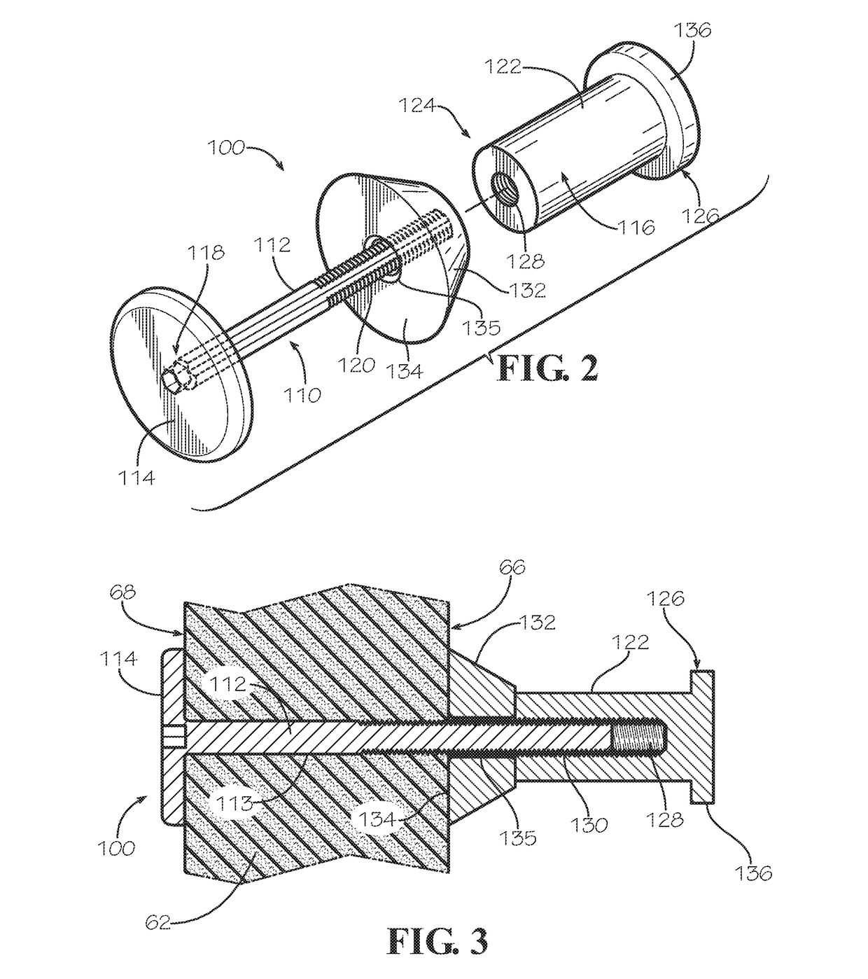
[0056]Referring now to the drawing in which like numbers indicate like elements throughout the several views, there is shown in FIG. 1 a disclosed embodiment of a removable insulated compound concrete form 10 in accordance with the present invention. The removable insulated compound concrete form 10 includes a first conventional removable concrete form 12 and a second conventional removable concrete form 14 vertically oriented and horizontally spaced from the first conventional removable concrete form. The first and second removable concrete forms 12, 14 are identical, so only the first removable concrete form will be described in detail. The removable concrete form 12 comprises a rectangular concrete forming first face panel 16 made of a strong material, such as wood or metal. Most prior art removable concrete forms have concrete forming face panels made from wood,...


PUM

PropertyMeasurementUnit
thicknessesaaaaaaaaaa
densityaaaaaaaaaa
timeaaaaaaaaaa

Abstract

The invention comprises a product. The product comprises a first removable concrete form having a concrete forming face and a first insulating panel insert having a first primary surface and an opposite second primary surface, wherein the second primary surface of the first insulating panel insert contacts the concrete forming face of the first removable concrete form. The product also comprises an elongate anchor member having an enlarged portion and an elongate portion, the elongate portion having a first end and an opposite second end, wherein the enlarged portion is disposed adjacent the first end and contacts the second primary surface of the first insulating panel insert and wherein the elongate portion extends through the first insulating panel insert and extends outwardly from the first primary surface of the first insulating panel insert. A method of using a removable insulated concrete form system is also disclosed.

Description

CROSS-REFERENCE TO RELATED APPLICATIONS[0001]This application claims the benefit of application Ser. No. 62 / 289,263 filed Jan. 31, 2016.FIELD OF THE INVENTION[0002]The present invention generally relates to insulated concrete forms. More particularly, the invention relates to a removable concrete form with a removable insulated panel liner. The present invention also relates to an insulated concrete form that is easier to assemble and easier to use. The present invention relates to a removable insulated compound concrete form in which the form can be removed leaving the insulation attached to the concrete. The present invention also relates to a removable insulated compound concrete form wherein the insulation can be removed after the concrete is at least partially cured. The present invention also relates to a removable insulated compound concrete form that results in stronger concrete cured therein. The present invention also relates to temperature and maturity sensors to monitor ...

Claims


Application Information

Patent Timeline
Patent Type & Authority Applications(United States)
IPC IPC(8): E04B1/16E04B5/32E04G17/14E04G11/08E04G11/38E04B1/41E04B2/84E04G9/06
CPCE04B1/16E04B2/84E04B5/32E04G9/06E04G11/08E04G17/0657E04B1/4121E04G17/14E04B2103/02E04G2017/0611E04G11/38E04G2009/028C04B28/04C04B28/08C04B40/04E04B1/161E04G9/10E04G17/0652E04B2/8647E04G21/06E04B5/36E04B5/48E04B2002/8682E04B2002/8688E04G17/0658E04C5/168E04G17/06
Inventor CIUPERCA, ROMEO ILARIAN
Owner CIUPERCA ROMEO ILARIAN
Learn More