Propulsion system assembly

Active Publication Date: 2017-08-03
ISRAEL AEROSPACE IND
View PDF0 Cites 25 Cited by
  • Summary
  • Abstract
  • Description
  • Claims
  • Application Information

AI Technical Summary

Benefits of technology

The subject matter of this patent is a propulsion system assembly that allows an air vehicle to continue its mission without needing to change the way it flies. This system is also designed to be flexible and easy to adapt to changing needs, while being cost-effective and efficient to implement.

Problems solved by technology

This refers to a situation in which a problem can occur in the propulsion system in some stages of the vectored thrust flight that can result in an uncontrolled crash of the air vehicle.
Such a situation is more dangerous in air vehicles that do not have helicopter type rotors that can otherwise mitigate the danger by providing the air vehicle with some gliding characteristics.
An alternative approach to survivability in case of propulsion system failure in other types of VTOL type air vehicles (and sometimes implemented as an additional safety feature in some helicopters) is to provide redundancy in the thrust generation capability, and while several ways are known for creating the redundancy required to overcome this problem, conventionally this comes with a reduction in performance and a significant increase in cost of ownership.
Conventionally, such changes are sometimes achieved by redesigning the propulsion system to meet the new needs, though this solution can often require costly investment in time, effort and resources to implement.

Method used


Image

  • Propulsion system assembly
  • Propulsion system assembly
  • Propulsion system assembly

Examples


Embodiment Construction

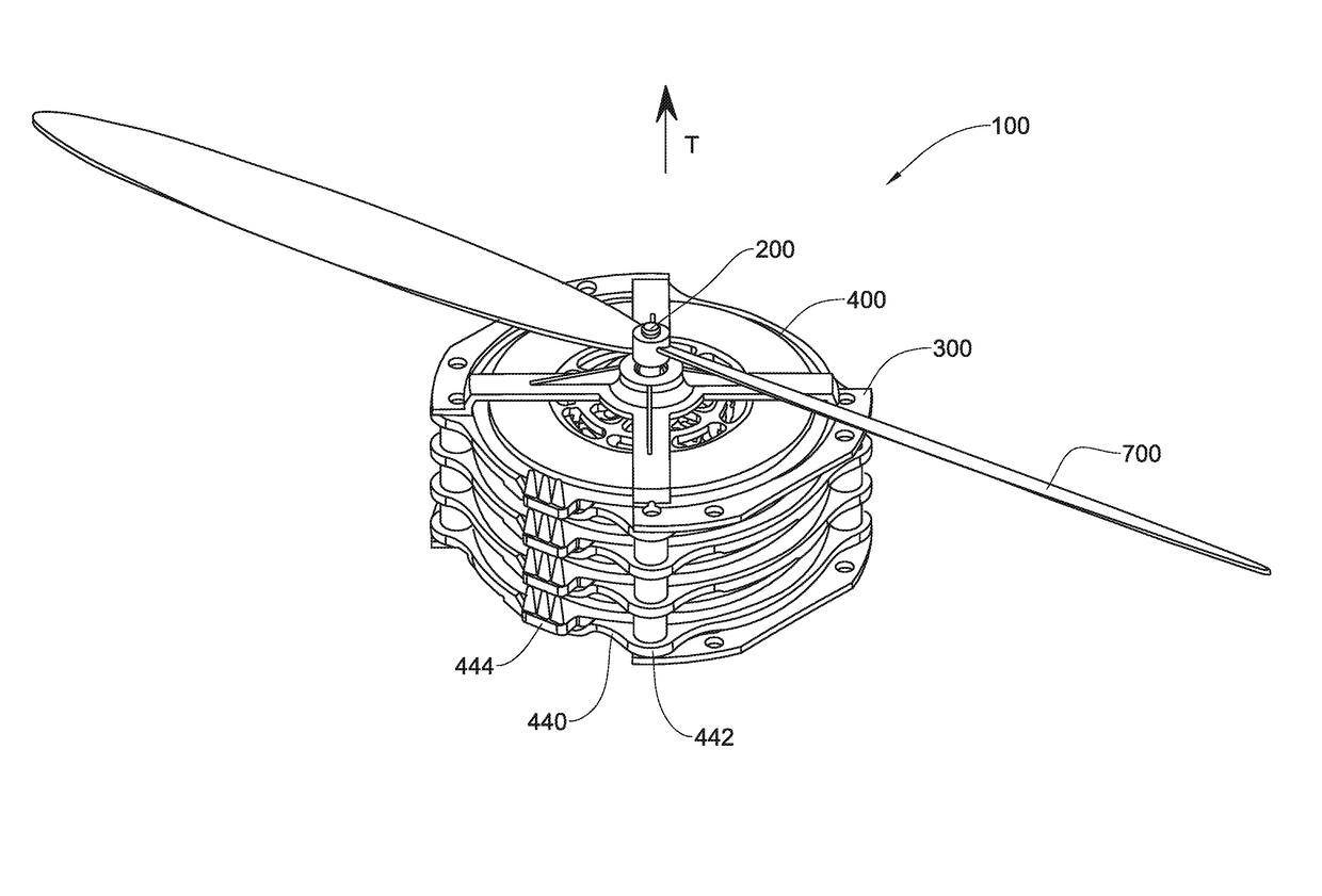
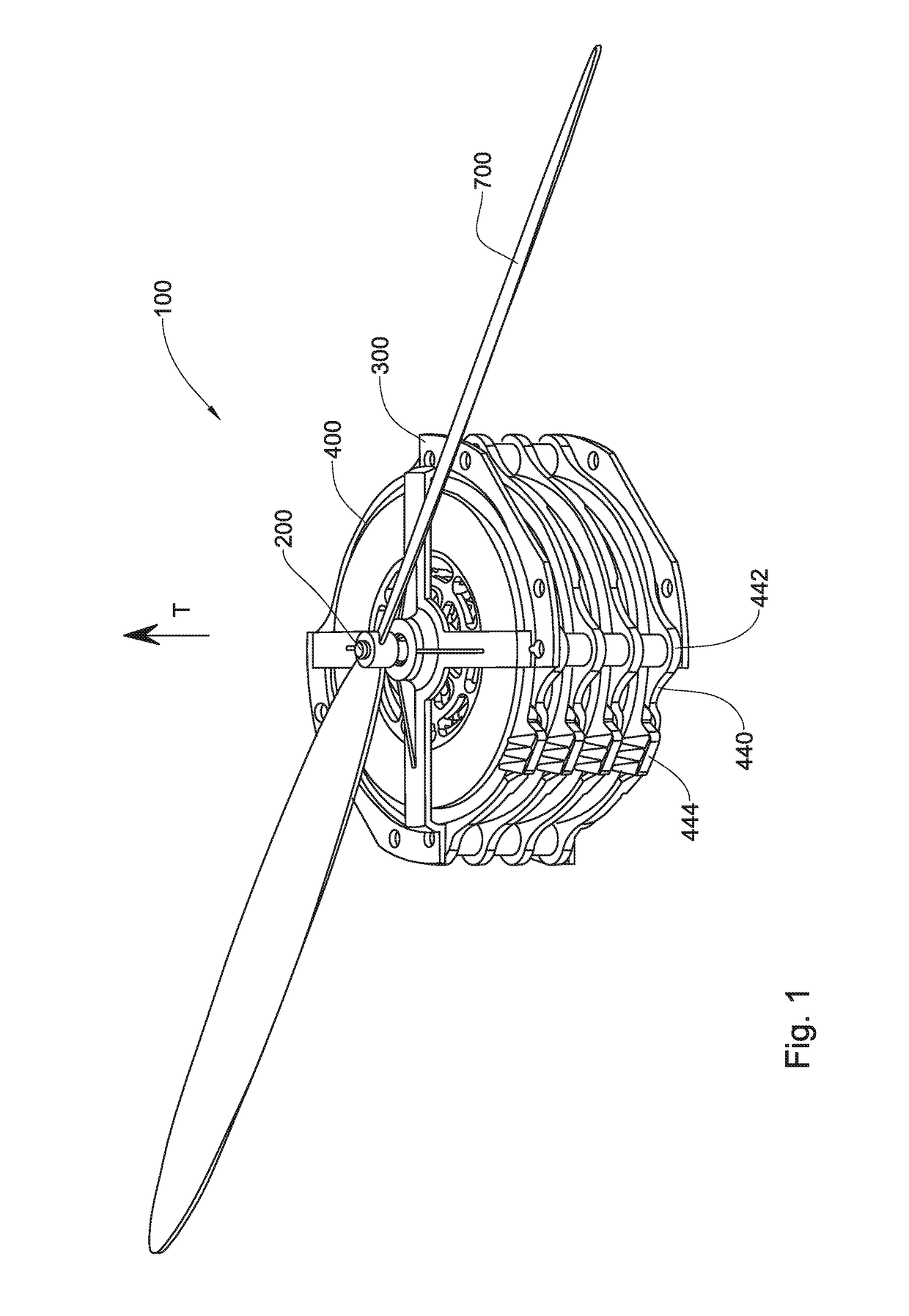
[0107]Referring to FIGS. 1 to 3, a propulsion system assembly according to a first example of the presently disclosed subject matter, generally designated 100, comprises a driveshaft 200, casing 300, and a plurality of electric motor modules (EMM) 400.

[0108]Referring to FIG. 2 in particular, each EMM 400 comprises in this example a first rotor 410 and a second rotor 420 sandwiching a stator 430 therebetween, and thus the first rotor 410 and the second rotor 420 are disposed one each on opposite facing sides of the stator 430.

[0109]The stator 430 is annular disc-shaped having a central opening 435, and includes a mounting ring 440 at the outer periphery thereof, the mounting ring 440 comprising a plurality of mounting points 442 as well as an electrical interface 444 including electrical inlet and / or outlet connection for providing electrical power to the EMM 400. The electrical interface 444 can also provide control inputs for controlling the EMM 400 and / or sensor outputs.

[0110]The ...


PUM


Abstract

A propulsion system assembly is provided including a driveshaft and a plurality of electric motor modules. The driveshaft is rotatably mounted to a casing about a drive axis, the driveshaft including a first shaft end and an opposite facing second shaft end. The plurality of electric motor modules are in axially stacked relationship with one another with respect to the drive axis to define an electric motor module stack, each electric motor module being configured for transmitting a torque to the driveshaft when coupled thereto independently of at least one other electric motor module. Each electric motor module includes a controllable clutch arrangement for selectively coupling and decoupling the respective electric motor module with respect to the driveshaft to respectively enable and disable transmission of torque between the respective electric motor module and the driveshaft.

Description

TECHNOLOGICAL FIELD[0001]The presently disclose subject matter relates to propulsion systems, in particular for powering air vehicles.BACKGROUND ART[0002]References considered to be relevant as background to the presently disclosed subject matter are listed below:[0003]U.S. Pat. No. 8,317,126[0004]U.S. Pat. No. 8,288,916[0005]U.S. Pat. No. 7,906,925[0006]U.S. Pat. No. 7,377,876[0007]U.S. Pat. No. 6,713,982[0008]US 2010 / 253168[0009]US 2008 / 006739[0010]WO 2011 / 107718[0011]WO 2010 / 071779[0012]WO 2014 / 033715[0013]WO 2014 / 033716[0014]DE 2134667[0015]Acknowledgement of the above references herein is not to be inferred as meaning that these are in any way relevant to the patentability of the presently disclosed subject matter.BACKGROUND[0016]There are many classes of air vehicles that use one or more propulsion system for conventional aerodynamic flight and / or for vectored flight.[0017]In at least some cases, electrically powered motors are used for powering the air vehicle and in any case...

Claims


Application Information

Patent Timeline
IPC IPC(8): B64D35/02B64C27/14
CPCB64D35/02B64C27/14B60L11/12H02K7/108H02K16/00B64C15/00B64D27/24H02K21/24H02K7/10H02K2213/12B60L50/15Y02T50/60Y02T50/40B64U50/19B64U50/14B64U50/13
Inventor REGEV, EYAL
Owner ISRAEL AEROSPACE IND
Why Eureka
Try Eureka