
Work vehicle

a technology for working vehicles and wiper motors, applied in the field of work vehicles, can solve the problems of inability to easily secure the support portion of the wiper motor, inability to assemble work such as bonding work, and inability to achieve forward visibility, so as to prevent an erroneous operation, easy to discriminate, and obtain information.

Active Publication Date: 2017-08-03
YANMAR POWER TECHNOLOGY CO LTD
View PDF3 Cites 9 Cited by
  • Summary
  • Abstract
  • Description
  • Claims
  • Application Information

AI Technical Summary

Benefits of technology

This patent is about a work vehicle with a wiper and wiper driving mechanism. The work vehicle has an air-cut plate attached to the steering column where the control steering wheel is arranged. The wiper driving mechanism is attached to the air-cut plate, which makes it easier to assemble and maintain the wiper and wiper driving mechanism. The vehicle also has switches that are easy to assemble and operate, improving the workability and operability of the operator. The technical effects are improved assembly and maintenance work of the wiper and wiper driving mechanism, as well as improved operability for the operator.

Problems solved by technology

In the meantime, in the structure in which the wiper is provided in the outer side of the windshield such as this kind of work vehicle, a wiper driving mechanism including a wiper motor driving the wiper is necessary, and there has been a problem that a support portion for the wiper motor can not be easily secured.
Further, since the windshield has been conventionally structured such as to be separated into three sections, an assembling work such as a bonding work is complicated, and a forward visibility is inhibited by a blind corner caused by the bonded portion.
Therefore, there has been a problem that an operator can not easily view the switches because the switches are under screen of a control steering wheel or an operation lever.
However, if the tilt lever or the telescopic lever is erroneously operated, there has been a problem that the posture of the control steering wheel comes to a posture which can not be expected by the operator.

Method used


Image

  • Work vehicle
  • Work vehicle
  • Work vehicle

Examples


Embodiment Construction

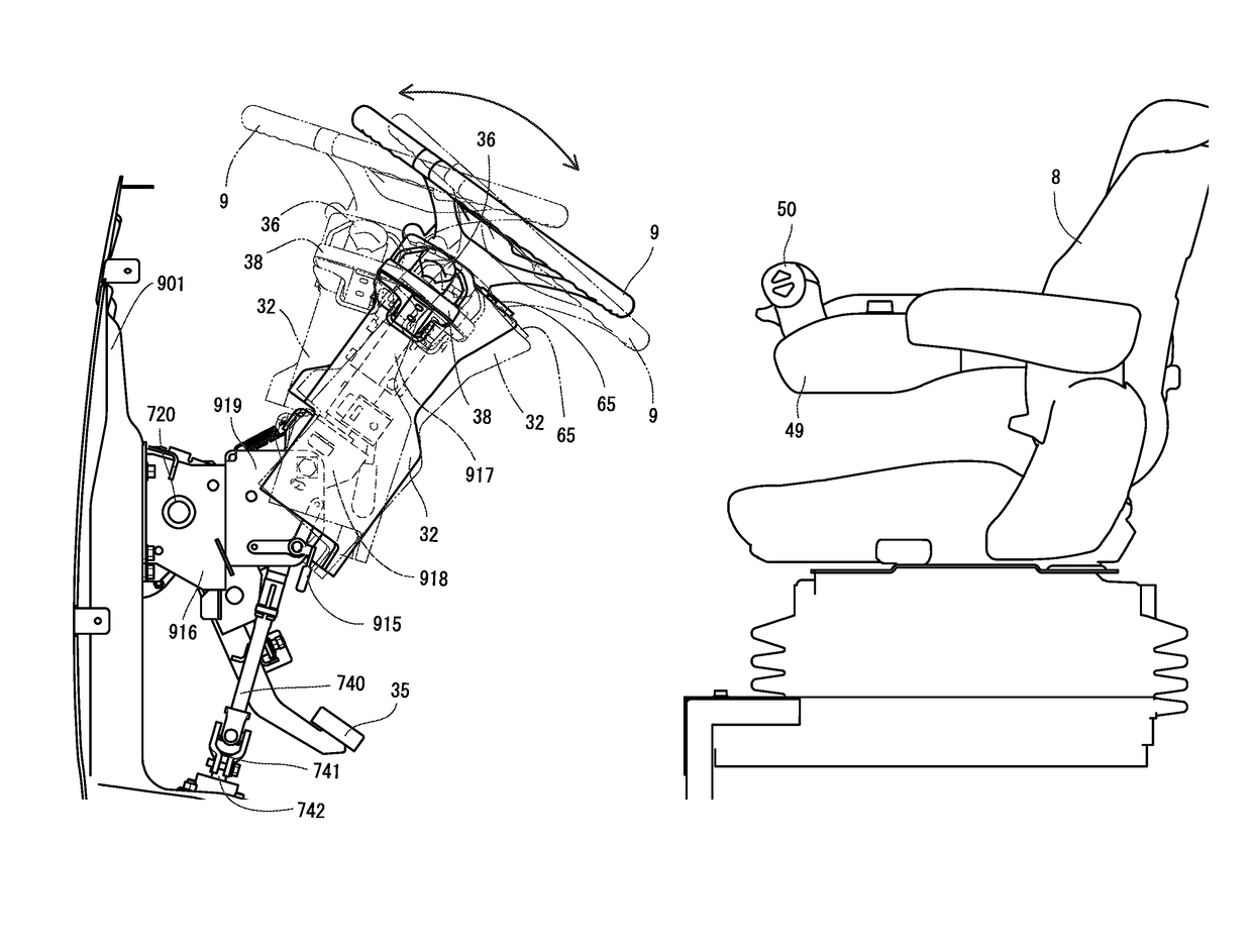
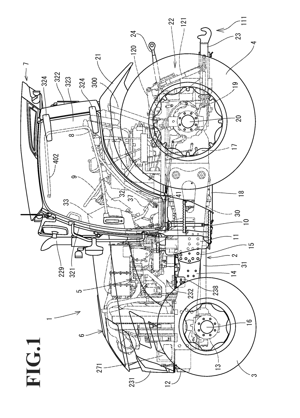
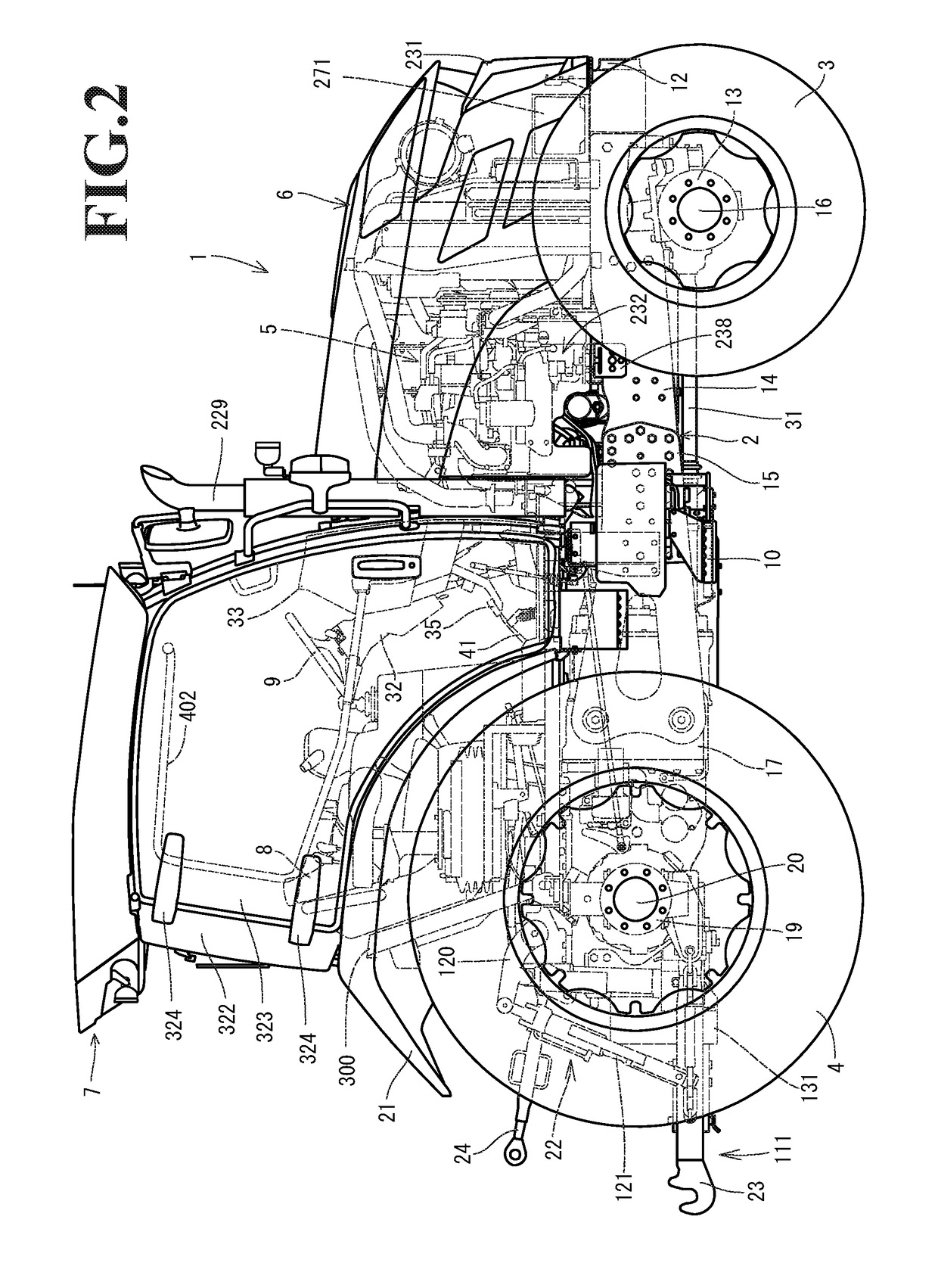
[0053]A description will be given below of an embodiment obtained by specifying the present invention on the basis of the accompanying drawings of a tractor for an agricultural work. As shown in FIGS. 1 to 8, a travel machine body 2 of a tractor 1 is supported by a pair of right and left front wheels 3 serving as a traveling portion and a pair of right and left rear wheels 4 serving as the traveling portion in the same manner. The pair of right and left rear wheels 4 correspond to a rear traveling portion. A diesel engine 5 (hereinafter, refer simply to as an engine) is mounted to a front portion of the travel machine body 2, and the tractor 1 is structured such as to travel forward and backward by driving the rear wheels 4 or the front wheels 3 by the engine 5. The engine 5 is covered with a hood 6. A cabin 7 is installed to an upper surface of the travel machine body 2. A control seat 8 and a control steering wheel 9 operating the front wheels 3 to steer are arranged in an inner p...


PUM


Abstract

The invention aims at providing a work vehicle in which an operator can easily view each of switches in spite of the work vehicle in which a plurality of switches such as a DPF regeneration switch, a working switch and a one-touch automatic switch are concentrically provided on a front surface of a control seat. In a work vehicle having a cabin which is inward provided with a control seat installed in a travel machine body, a DPF regeneration switch, a working switch, and a one-touch automatic switch are provided. The DPF regeneration switch is provided on an upper surface of a steering column in a base portion of a control steering wheel, and the DPF regeneration switch is arranged in a field of vision of an operator under a straight moving work posture.

Description

CROSS-REFERENCE TO RELATED APPLICATIONS[0001]The present application is a continuation application of International Application No. PCT / JP2015 / 078382, filed Oct. 6, 2015, which claims priority to Japanese Patent Application No. 2014-217215, filed Oct. 24, 2014, and Japanese Patent Application No. 2015-082009, filed Apr. 13, 2015. The contents of these applications are incorporated herein by reference in their entirety.BACKGROUND OF THE INVENTION[0002]The present invention relates to a work vehicle.[0003]In the work vehicle such as the tractor or the wheel loader, there are arranged around a control seat a control steering wheel for operating to steer a travel machine body and a plurality of lever members for setting and adjusting a traveling state of the travel machine body, taking an operability into consideration. For example, the tractor for the agricultural work has a main transmission lever, a sub transmission lever, a forward and backward movement switching lever, and a PTO sh...

Claims


Application Information

Patent Timeline
Patent Type & Authority Applications(United States)
IPC IPC(8): B62D1/04B62D1/185B60R16/023B62D1/08B62D1/10B60K37/04B62D1/189
CPCB62D1/046B60K37/04B62D1/185B62D1/189B62D1/08B62D1/10B60R16/023B60Y2200/221B62D1/18B62D21/186B62D49/06B60K35/10B60K2360/61B62D1/16B60R16/02B60K35/00B60Y2200/415B62C1/08B60K35/50
Inventor HIGASHIGUCHI, GAKU
Owner YANMAR POWER TECHNOLOGY CO LTD
Learn More