
Anode, and x-ray generating tube, x-ray generating apparatus, and radiography system using the same

a technology of generating tube and generating apparatus, which is applied in the direction of x-ray tube target and convertor, material analysis using wave/particle radiation, instruments, etc., can solve the problems of difficult to secure a necessary x-ray output, and achieve highly reliable x-ray generating tube, inhibit crack development, and high reliability

Active Publication Date: 2017-07-27
CANON KK
View PDF5 Cites 1 Cited by
  • Summary
  • Abstract
  • Description
  • Claims
  • Application Information

AI Technical Summary

Benefits of technology

The present invention provides an anode for an X-ray generating tube that reduces a risk of vacuum leakage and cracking, resulting in a highly reliable X-ray generating apparatus and improved image quality. The anode alleviates compression stress and inhibits crack development, ensuring a long-term and safe use of the X-ray generating tube.

Problems solved by technology

In such an X-ray generating tube including the transmission target as an end window, when X-ray generating operation is repeated, a desired tube current sometimes cannot be obtained and hence it is difficult to secure a necessary X-ray output.

Method used


Image

  • Anode, and x-ray generating tube, x-ray generating apparatus, and radiography system using the same
  • Anode, and x-ray generating tube, x-ray generating apparatus, and radiography system using the same
  • Anode, and x-ray generating tube, x-ray generating apparatus, and radiography system using the same

Examples


first embodiment

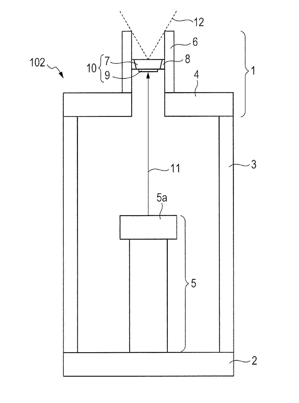
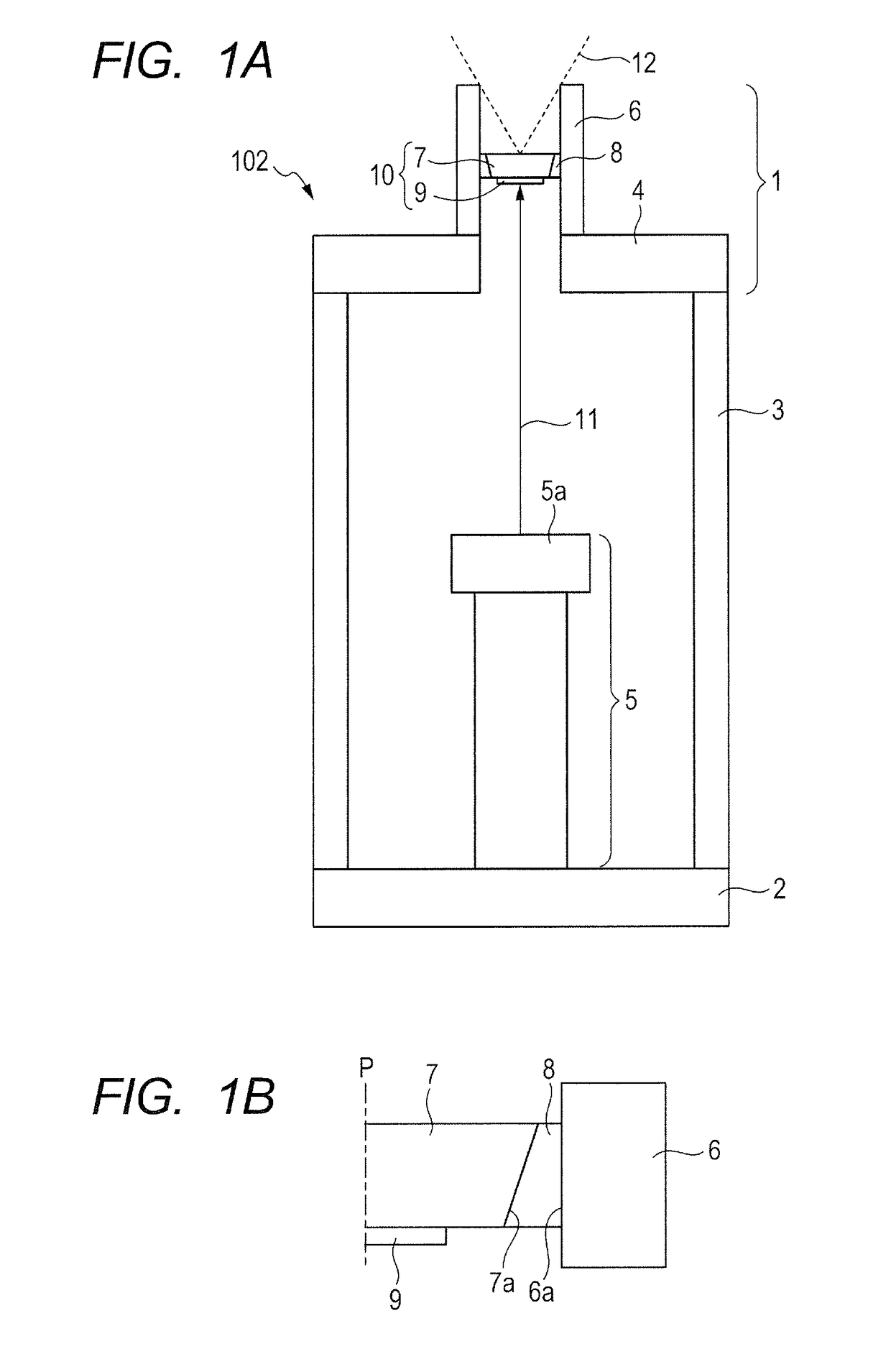
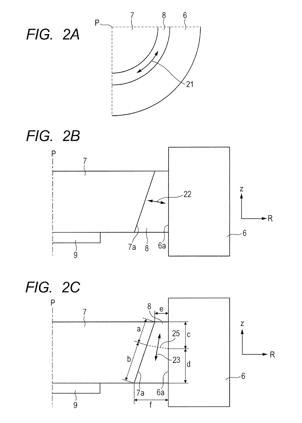
[0057]An anode 1 according to a first embodiment of the present invention is described. This case is a case in which the tubular anode member 6 is cylindrical and the transmitting substrate 7 of the target 10 is in the shape of a disk that is a concentric circle with the inner circumference of the tubular anode member 6 in plan view. As illustrated in FIG. 1B, in the anode of the present invention, the bonding material 8 has a thickness that varies in a direction along a central axis P of the tubular anode member 6 (hereinafter referred to as “central axis P”). Note that, in the present invention, the thickness of the bonding material 8 is a width of the bonding material 8 in a direction orthogonal to the central axis P of the tubular anode member 6, that is, in this case, a width of the bonding material 8 in a radial direction of the tubular anode member 6, and, a width of the drawing sheet of FIG. 1B in a lateral direction. Note that, the bonding material 8 has the uniform thickne...

second embodiment

[0079]FIG. 5 is a partial sectional view for schematically illustrating a structure of an anode according to another exemplary embodiment of the present invention. In this embodiment, the transmitting substrate 7 has a support surface 7b for supporting the target layer 9. Further, the tubular anode member 6 has a tube inner circumference for supporting the transmitting substrate 7. Further, the tubular anode member 6 of this embodiment includes a ring-shaped protruding portion 41 that protrudes inward in a tube radial direction from the tube inner circumference, which is a point of the tubular anode member of this embodiment that is different from that of the first embodiment described with reference to FIG. 1A to FIG. 3B. The ring-shaped protruding portion 41 has a bearing surface 41a opposed to a periphery of the support surface 7b. The bonding material 8 extends from a gap in a tube axial direction that extends in the direction of the tube axis between the side surface 7a and the...


PUM

PropertyMeasurementUnit
atomic numberaaaaaaaaaa
diameteraaaaaaaaaa
diameteraaaaaaaaaa

Abstract

A thickness of a bonding material (8) is varied in a radial direction orthogonal to a central axis (P) of the tubular anode member (6), the bonding material (8) being used for bonding a transmitting substrate (7) for supporting a target layer (9) and a tubular anode member (6) in a direction along the central axis (P). Thus, a region in which a circumferential tensile stress of the bonding material (8) is alleviated is formed in the direction along the central axis (P) to prevent a crack from developing in the bonding material (8).

Description

TECHNICAL FIELD[0001]The present invention relates to an anode to be used in an X-ray generating tube and including a transmission target, and also relates to an X-ray generating tube including the anode, an X-ray generating apparatus including the X-ray generating tube, and a Radiography system including the X-ray generating apparatus.BACKGROUND ART[0002]A transmission type X-ray generating tube including a transmission target is known. The transmission target uses an X-ray emitted from a side thereof, which is opposite to a side, on which an electron beam enters the target. The transmission type X-ray generating tube may include a target as an end window of the X-ray generating tube. Such a transmission type X-ray generating tube has advantageous features in that a radiation angle can become wider, heat dissipation performance can become higher, and an X-ray generating apparatus can be downsized. The target in such a transmission type X-ray generating tube is hermetically bonded t...

Claims


Application Information

Patent Timeline
Patent Type & Authority Applications(United States)
IPC IPC(8): H01J35/08G01N23/04
CPCH01J35/08G01N23/04H01J2235/186H01J2235/083H01J2235/087H01J35/186H01J35/116H05G1/10H01J2235/086H01J35/12H05G1/02H05G1/025H01J35/02G01N2223/308H01J35/32H01J35/165H01J1/94H01J2237/032H01J2237/036H01J37/023H01J2235/085H01J2235/08
Inventor OHASHI, YASUOUEDA, KAZUYUKI
Owner CANON KK
Learn More