Self-latching and self-locking latch system for sliding door panels

a latch system and sliding door technology, applied in building locks, construction, building components, etc., can solve the problems of deformation or damage to the frame or the door itself, wind damage, deformation or damage to the door, etc., to reduce the steps required and simplify the procedures for latching and locking.

Inactive Publication Date: 2017-07-27
MORTON BUILDINGS
View PDF2 Cites 2 Cited by
  • Summary
  • Abstract
  • Description
  • Claims
  • Application Information

AI Technical Summary

Benefits of technology

[0005]The invention is generally directed to locking and securing assemblies, which among other things, address the aforementioned needs, simplify the procedures for latching and locking and reduce the steps required to provide access without compromising security.
[0026]In some embodiments, the latching retainer device is attached to the jamb of a sliding door which extends outward from the jamb into the frame area in the central part of the door and which drives outward after the vertical member at the edge of the panel has passed the edge of the jamb and latches the door in the open position, which among other things, facilitates a non-friction positive capture of the open panel such that the door cannot slip back partially into the opening and hence be vulnerable to wind damage.

Problems solved by technology

If any of these door arrangements are not properly secured, wind damage can occur.
In fact, a sudden gust of wind may dislodge the doors from the track or tracks.
Such wind damage may also cause deformation or damage to the frame or the door itself in cases where the door is inadequately supported.

Method used


Image

  • Self-latching and self-locking latch system for sliding door panels
  • Self-latching and self-locking latch system for sliding door panels
  • Self-latching and self-locking latch system for sliding door panels

Examples


Embodiment Construction

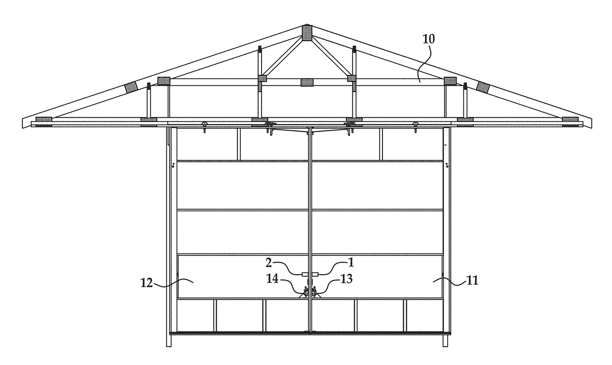
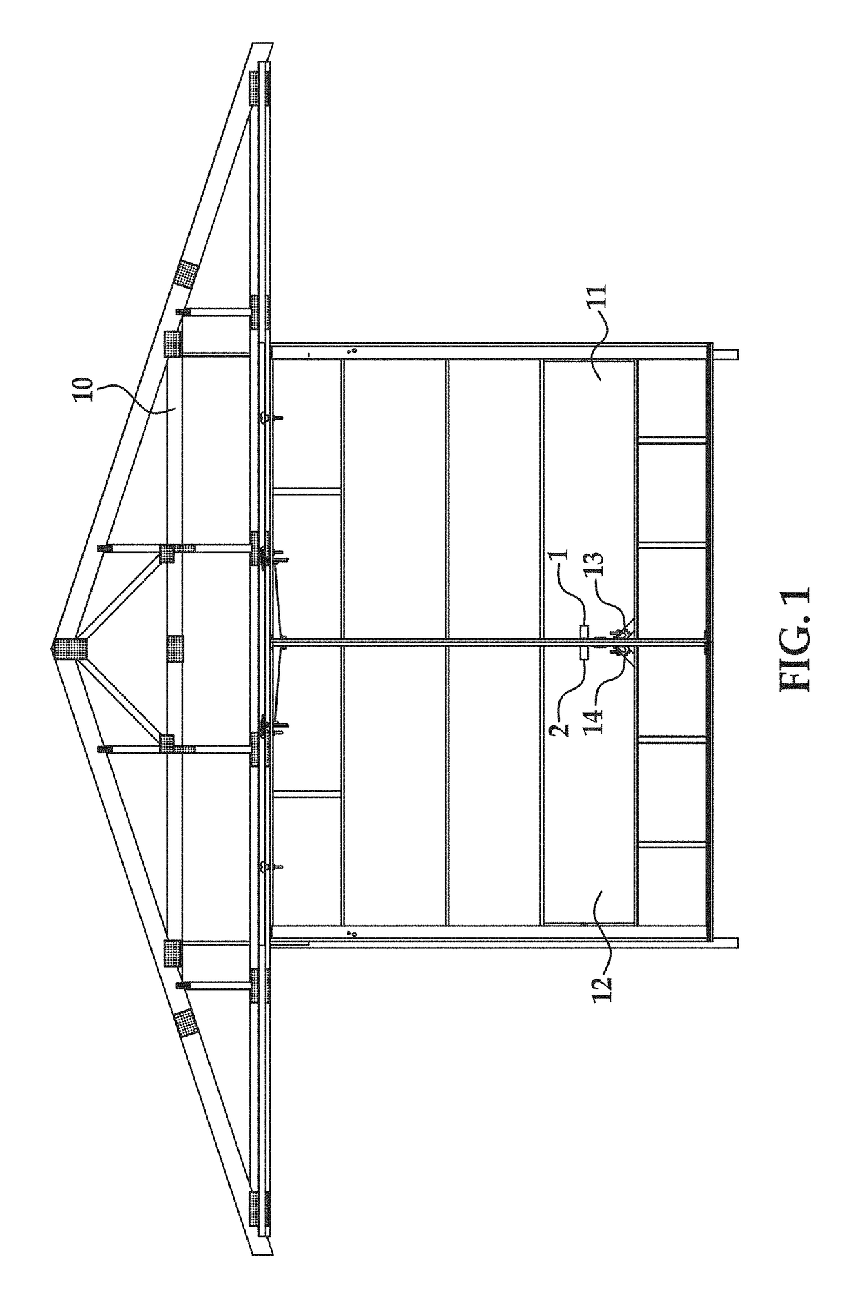
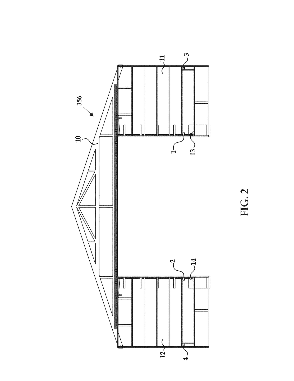
[0080]With reference to the drawings, and in operation, the present invention overcomes at least some of the disadvantages of known sliding doors by providing a self-latching, self-locking latch system for use with sliding door panels.

[0081]In one embodiment, the system includes a cable system that runs horizontally to a door jambs and uses a retainer mechanism to keep individual door panels on a floor guide system if they are not latched to each other. For example, in one embodiment, the system may include the features described in FIGS. 22-34.

[0082]The following description contains illustrations of devices, systems and methods according to the invention for purposes of promoting an understanding of embodiments the invention, among other things. It should be understood that the scope of the invention is not limited by these embodiments. Alterations and modifications of the features of the invention, as well as additional applications of its principles in other forms or embodiments...


PUM


Abstract

A door retention system for use with a building is described herein. The building includes a frame and a sliding door. The door retainer system includes a door retainer coupled to the frame and a latch retainer assembly coupled to the sliding door. The door retainer includes a housing coupled to the frame and a retainer bolt extending outwardly from the housing. The latch retainer assembly includes a retainer catch coupled to the sliding door and a pivot catch coupled to the retainer catch. The retainer catch includes a slot defined along an outer surface of the retainer catch configured to receive the retainer bolt therein as the sliding door is moved from the open position to the closed position. The pivot catch is movable between a latched position and an unlatched position and configured to engage the retainer bolt in the latched position.

Description

CROSS-REFERENCE TO RELATED APPLICATIONS[0001]This application is a continuation-in-part of U.S. Non-Provisional patent application Ser. No. 14 / 638,792, filed March 4, 2015, which is a continuation of U.S. Non-Provisional patent application Ser. No. 13 / 211,209 (now U.S. Pat. No. 8,998,274, issued on Apr. 7, 2015), filed Aug. 16, 2011, which claims priority to U.S. Provisional Application No. 61 / 374,545 filed Aug. 17, 2010, and claims priority to U.S. Provisional Application No. 62 / 091,375 filed Dec. 12, 2014, the disclosures of which are incorporated herein.BACKGROUND OF THE INVENTION[0002]Horizontal sliding doors, which actually may slide or roll, usually include one or more door panels suspended by carriages that travel along an overhead track. The carriages allow the door panels to slide or roll in a generally horizontal direction in front of a doorway to open and close the door. The door may be manually or automatically moved from its open and closed position. Sliding doors such ...

Claims


Application Information

Patent Timeline
Patent Type & Authority Applications(United States)
IPC IPC(8): E05C1/16E06B3/46E05C1/08
CPCE05C1/16E06B3/4636E05C1/08E05B65/0823E05B65/087E05C2007/007E05B53/003
Inventor FEHR, DAVEKNEPP, WAYNE A.
Owner MORTON BUILDINGS
Why Eureka
Try Eureka