
Display device of operation state of automobile brake

a technology of display device and operation state, which is applied in the direction of signalling/lighting device, vehicle components, optical signalling, etc., can solve the problems of difficult to make the pedestrian notice a warning, inability to understand, and serious accidents

Inactive Publication Date: 2017-07-27
ISHIDA MITSUNORI
View PDF8 Cites 7 Cited by
  • Summary
  • Abstract
  • Description
  • Claims
  • Application Information

AI Technical Summary

Benefits of technology

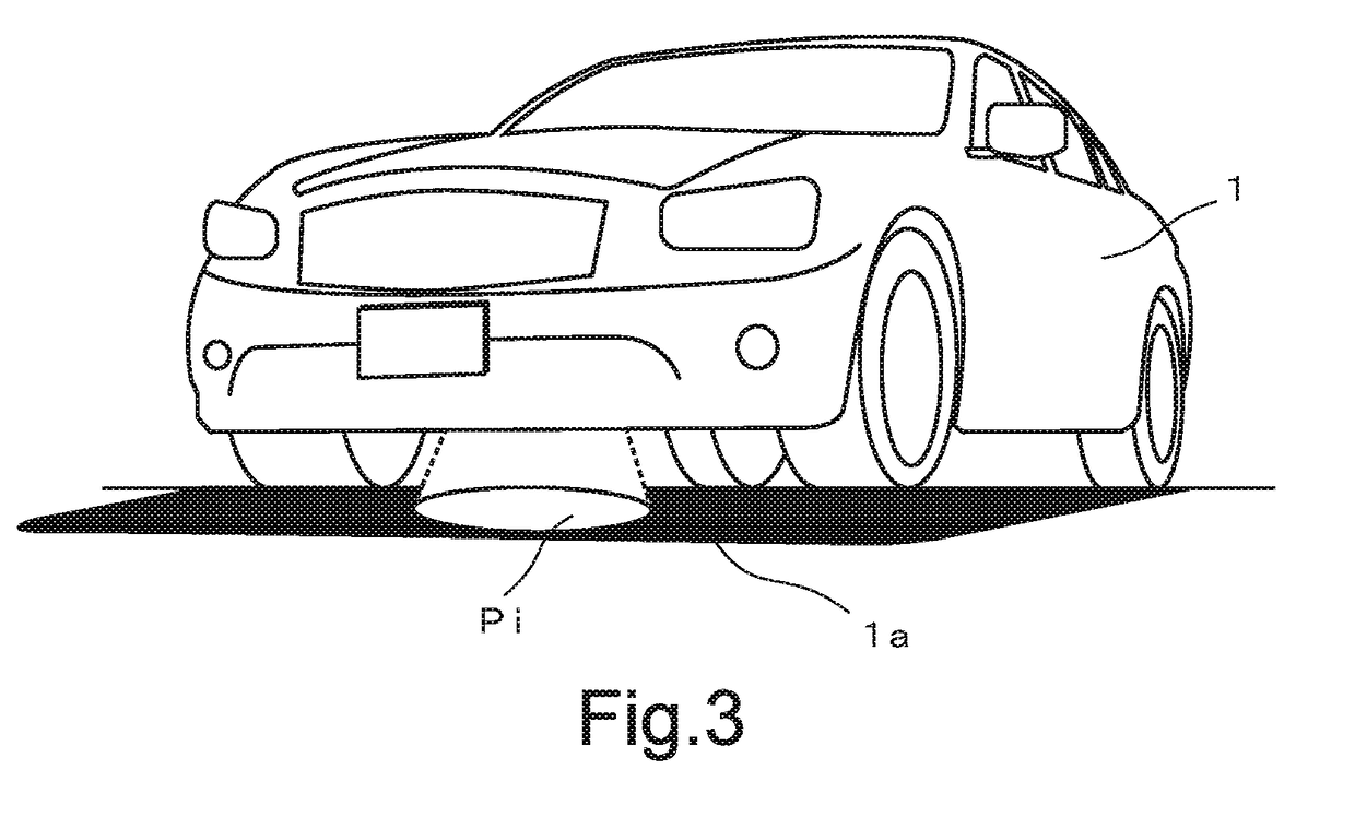
The present invention is about improving safety for pedestrians who need to cross in front of an automobile. The invention involves projecting an optical image onto the shadow of the automobile body, making it easier for the pedestrian to determine if the automobile is stopped or if it is in gear. The image can include characters, figures, patterns, and symbols. Additionally, the invention also displays the brake status of a following automobile on the driving mirror, allowing the pedestrian to see if there is a risk of a collision. The invention is designed to provide information to the pedestrian in a clear and effective way, increasing safety for everyone.

Problems solved by technology

However, for example, when a pedestrian attempts to cross a road in front of an automobile at a place without a traffic light machine, whether the automobile stops while giving careful caution to the pedestrian or whether the automobile continues to stop without starting during the stopping of the automobile cannot be understood by merely seeing the automobile.
There is a case in which the automobile starts without noticing the pedestrian because of the carelessness of a driver of the automobile even if the automobile is stopped, and there is a danger that a serious accident will be caused if the driver is slow to become aware of the pedestrian.
However, the time that makes it possible to brightly illuminate the road surface in front of the pedestrian by projecting a laser beam is limited to nighttime, and it is difficult to make the pedestrian notice a warning even if a laser beam is projected during the daytime during which the environment around the pedestrian is bright.
Additionally, even if it becomes possible to brightly illuminate the road surface in front of the pedestrian with a laser beam when the forward sensor is used in the nighttime, a laser beam, instead of an alarm whistle, is merely projected to illuminate it, and, even when the automobile is stopped, it is impossible to determine whether the automobile is stopped in a state of being ready to start at any time or whether there is a danger that the automobile will suddenly start.

Method used


Image

  • Display device of operation state of automobile brake
  • Display device of operation state of automobile brake
  • Display device of operation state of automobile brake

Examples


example 1

[0039]In this example, the brake operation detection switch Bp is in an ON state, the shift operation detection switch Sf (Sd) is in an ON state, and the parking brake operation detection switch Sd is in an ON state and an OFF state (i.e., Sd1 is in an OFF state, and Sd2 is in an ON state).

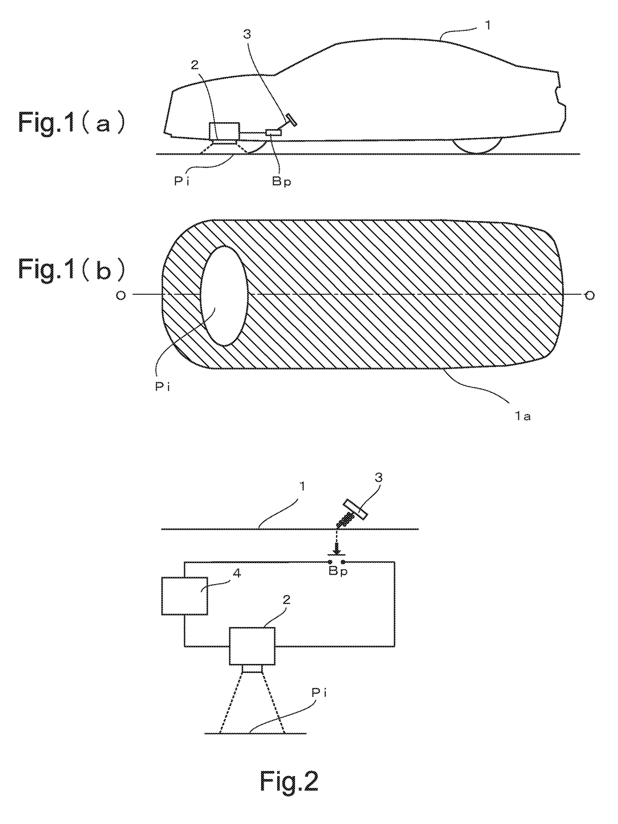
[0040]At this time, the brake is applied by depressing the brake pedal 3, and the shift lever 6 is set at the drive position, and the parking brake 7 is in a state of not being applied. This applies to most cases such as a case in which the automobile travels and then stops at an intersection or short of a pedestrian crossing or a case in which the automobile temporarily stops at a temporary stop line, and, besides, a case in which the automobile stops to avoid danger. In this state, if the depressing of the brake pedal 3 is released, it becomes possible for the automobile to immediately go straight. The controller 5 regards this state as “Caution is required,” and outputs the command of “Caution”...

example 2

[0041]In this example, the brake operation detection switch Bp is in an ON state, the shift operation detection switch Sf (Sp) is in an ON state, and the parking brake operation detection switch Sd is in an ON state and an OFF state (i.e., Sd1 is in an ON state, and Sd2 is in an OFF state).

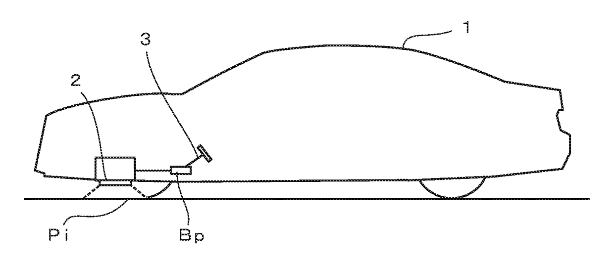
[0042]At this time, from the reason that the automobile must be stopped so long as the shift lever 6 selects “Parking” and so long as the parking brake 7 is applied, the controller 5 regards this state as “Safe” and outputs the command of “Safe” to the light emitting device 2. An optical projection image Pi of a luminous color that arouses tentative caution, such as a white or blue luminous color, is projected from the light emitting device 2 to the shadow of the automobile body 1 as a caution arousing sign.

example 3

[0043]In this example, the brake operation detection switch Bp is in an ON state, the shift operation detection switch Sf (Sp) is in an ON state, and the parking brake operation detection switch Sd is in an OFF state and an ON state (i.e., Sd1 is in an OFF state, and Sd2 is in an ON state).

[0044]This example shows a state in which the application of the parking brake 7 has been released from the state of (Example 2). This state is considered as a state of being about to start now, and therefore the controller 5 regards this state as “Caution is required,” and outputs the command of “Urgent warning” to the light emitting device 2. For example, a redly flickering projection image Pi, which indicates an urgent warning, is projected from the light emitting device 2 to the shadow of the automobile body 1 as a caution arousing sign.


PUM


Abstract

[OBJECT] To clearly awaken a pedestrian who crosses in front of an automobile to the fact that an automobile driver is depressing a brake pedal.[ACHIEVING MEANS] The invention is a display device of operation state of automobile brake that includes a brake operation detection switch (Bp) and a light emitting device (2). The brake operation detection switch (Bp) is actuated by depressing a brake pedal (3) and outputs a brake actuating signal to the light emitting device (2). The light emitting device (2) is disposed on an undersurface of a front of an automobile body (1), and emits diffused light in a fixed range of the front of the automobile body by receiving an input of the brake actuating signal so that the diffused light forms an optical projection image (Pi) on a road within a range of a shadow of the automobile body (1) as a caution arousing sign. Apedestrian looks at the opticalprojection image (Pi) displayed in the shadow (1a) of the automobile body (1), and ascertains that a brake operation is being performed, thus enabling the pedestrian to cross a pedestrian crossing at ease.

Description

TECHNICAL FIELD[0001]The present invention relates to a device that displays an operation state of an automobile brake.BACKGROUND ART[0002]A brake lamp of an automobile is disposed at the rear of an automobile body in order to avoid being struck from behind. To alert another automobile there behind, a red luminous color is used. The brake lamp is usually used together with a back light, and the reason why a redly luminous lamp is used as the back light is that a caution-arousing display is made to alert a following automobile there behind or to alert pedestrians. As thus described, an automobile is provided with a caution-arousing lamp at its rear part.[0003]However, for example, when a pedestrian attempts to cross a road in front of an automobile at a place without a traffic light machine, whether the automobile stops while giving careful caution to the pedestrian or whether the automobile continues to stop without starting during the stopping of the automobile cannot be understood...

Claims


Application Information

Patent Timeline
Patent Type & Authority Applications(United States)
IPC IPC(8): B60Q1/44
CPCB60Q1/442B60Q1/0035
Inventor ISHIDA, MITSUNORI
Owner ISHIDA MITSUNORI
Learn More