
Video encoding and decoding with improved error resilience

a video and error resilience technology, applied in the field of digital signal processing, can solve the problems of inability to correctly parse the data of the encoder, the method is very vulnerable to transmission errors, and the inability to parse the bitstream correctly

Active Publication Date: 2017-07-20
CANON KK
View PDF5 Cites 4 Cited by
  • Summary
  • Abstract
  • Description
  • Claims
  • Application Information

AI Technical Summary

Benefits of technology

This approach allows correct parsing of the bitstream even in the presence of transmission errors, ensuring decoder synchronization without compromising compression efficiency by using spatial and temporal motion information predictors that can be computed from encoded data.

Problems solved by technology

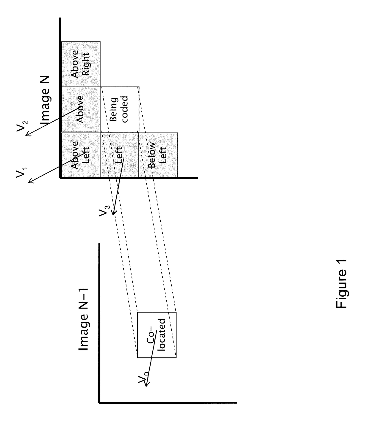
Therefore, the decoder cannot find how many bits were used for encoding the index of the motion vector predictor for the block ‘being coded’, and consequently the decoder cannot correctly parse the data for the slice because it cannot find where the index encoding stops and the encoding of video data starts.
Therefore, the fact that the number of bits used for signaling the motion vectors predictors depends of the values taken by the motion vector predictors makes the method very vulnerable to transmission errors, when the bitstream is transmitted to a decoder on a lossy communication network.
In case of packet losses, when some motion vector residual values are lost, it is impossible for the decoder to determine how many bits were used to encode an index representing the motion vector predictor has been encoded, and so it is impossible to parse the bitstream correctly.
Such an error may propagate causing the decoder's de-synchronization until a following synchronization image, encoded without prediction, is received by the decoder.
However, the coding efficiency is significantly decreased, since the temporal motion vector predictor is no longer used.
Therefore, this solution is not satisfactory in terms of compression performance.
However, this proposal fails to achieve the result of ensuring correct parsing at the decoder in some cases.
In that case, the value of a motion vector of the set of predictors is unknown, and the parsing problem at the decoder occurs.

Method used


Image

  • Video encoding and decoding with improved error resilience
  • Video encoding and decoding with improved error resilience
  • Video encoding and decoding with improved error resilience

Examples


first embodiment

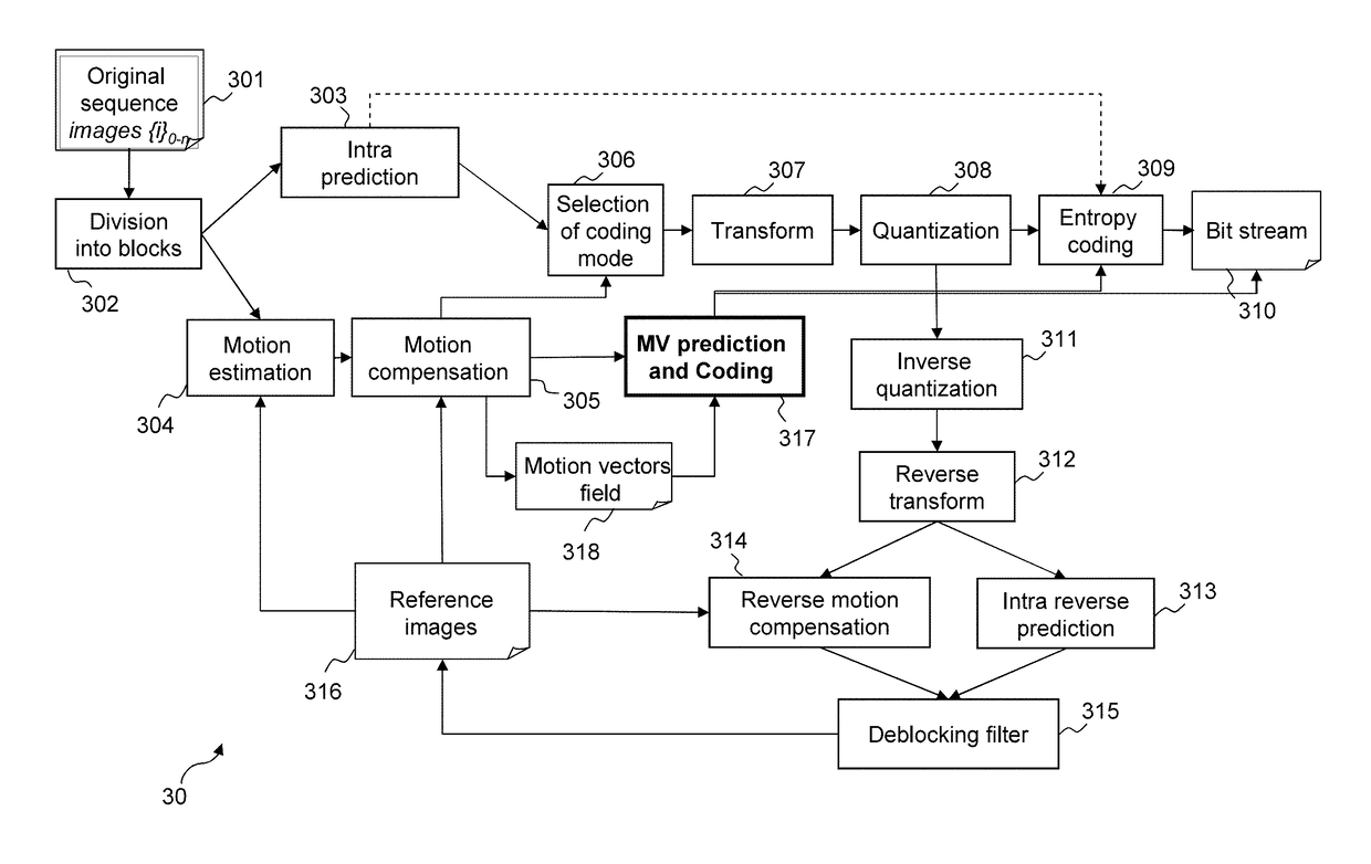
[0144]In a first embodiment, MVP′curr is set to the motion vector residual Vres encoded for MVPcurr. Taking the example of FIG. 5, if MVPcurr is the motion vector (VP) of block 508, which is encoded using the motion vector Vcol of the co-located block 510: MVPcurr=Vcol+Vres, where Vres is the motion vector residual actually encoded for block 508. Then, in this embodiment, MVP′curr is set to Vres.

second embodiment

[0145]In a second embodiment, MVP′curr is set to a predetermined vector, for example to the value (0,0).

third embodiment

[0146]In a third embodiment, a value which is predetermined or which can be retrieved by the decoder is added to the motion vector residual to obtain MVP′curr.

[0147]For example, Vres is added to another motion vector of S1, if any, which is encoded without dependencies on other slices. A predetermined order of parsing the set of vectors of S1 to find such a suitable motion vector predictor can be applied, both at the encoder and at the decoder. Taking the example of FIG. 5, if MVPcurr is the motion vector associated with block 508, the motion vector of block 504 can be used, which is the first motion vector encoded without temporal dependency encountered S1 for example.

[0148]Alternatively, a motion vector V to be used for the prediction can be transmitted from the encoder to the decoder in the slice header. Then, MVP′curr=Vres+V. The motion vector V can be computed as one of the following:[0149]the average or the weighted average of the motion vectors of the co-located slice of slic...


PUM


Abstract

A portion of an image, belonging to a current encoding unit, is encoded by motion compensation with respect to a reference image portion indicated by an item of motion information. A motion information predictor is selected from among a set of motion information predictors and the item of motion information is encoded with respect to said motion information predictor. The set of motion information predictors used is permitted to include at least one temporal motion information predictor associated with an image portion of a previous image of said sequence but is not permitted to include any spatial motion information predictor that is unobtainable from encoded data of said current encoding unit, for example a spatial motion information predictor that was itself encoded with respect to a temporal motion information predictor.

Description

CROSS-REFERENCE TO RELATED APPLICATIONS[0001]This application is a continuation, and claims the benefit, of U.S. patent application Ser. No. 13 / 346,012, presently pending and filed on Jan. 9, 2012, and claims the benefit under 35 U.S.C. §119(a)-(d) of United Kingdom Patent Application No. 1100434.8, filed on Jan. 11, 2011 and entitled “Video encoding and decoding with improved error resilience”.[0002]The above cited patent applications are hereby incorporated by reference herein in their entireties.BACKGROUND OF THE INVENTION[0003]Field of the Invention[0004]The invention relates to a method and device for encoding a sequence of digital images and a method and device for decoding a corresponding bitstream.[0005]The invention belongs to the field of digital signal processing, and in particular to the field of video compression using motion compensation to reduce spatial and temporal redundancies in video streams.[0006]Description of the Related Art[0007]Many video compression formats...

Claims


Application Information

Patent Timeline
Patent Type & Authority Applications(United States)
IPC IPC(8): H04N5/14H04N19/513H04N19/573H04N19/55H04N19/139H04N19/527H04N19/53H04N19/533H04N19/52H04N19/57
CPCH04N5/145H04N19/52H04N19/513H04N19/573H04N19/55H04N19/139H04N19/527H04N19/53H04N19/533H04N19/57
Inventor LAROCHE, GUILLAUMEONNO, PATRICE
Owner CANON KK
Learn More