Simulation device and method for simulation

Active Publication Date: 2017-07-20
DSPACE DIGITAL SIGNAL PROCESSING & CONTROL ENG
View PDF4 Cites 0 Cited by
  • Summary
  • Abstract
  • Description
  • Claims
  • Application Information

AI Technical Summary

Benefits of technology

The invention is a device that improves the simulation of electrical behavior in complex peripheral circuit arrangements, such as motor windings. It can create nonlinear current and voltage curves with changing current directions, which is more realistic than simply simulating a resistance. This results in better testing of control device characteristics and optimization of controller performance. Overall, the device provides a more meaningful test for the actual operating mode of the circuit arrangement.

Problems solved by technology

Depending on the requirements for the dynamics of the circuit for simulation, and depending on the nature of the requirements for avoiding or at least reducing an unwanted superposition of ripple currents on the current in the bridge shunt arm or superposition of an unwanted—possibly high-frequency—AC current on the current in the bridge shunt arm, conventional controllable voltage sources could prove to be inadequate for highly precise simulation applications.
A problem frequently encountered with prior art electric motor simulation devices is that they either do not adequately emulate reality, or the prior art electric motor simulation devices cannot be retrofitted with sufficient flexibility to changed electric motors that are to be simulated, or else such retrofits require very extensive hardware changes that are time-consuming.
The simulation devices heretofore available, in particular the simulation devices suitable for so-called “hardware-in-the-loop simulation,” abbreviated “HIL simulation,” are lacking in adequate scalability and adaptability, which is to say that the scaling and adapting of previous simulation devices, for the purpose of, e.g., adaptation of the simulation device to different inductive loads to be simulated, requires extensive hardware changes in many cases.
Frequently, it has only been possible heretofore to solve the problems resulting from the described inadequate scalability and inadequate adaptability through rebuilding or retrofitting work on the simulation device, especially when the electrotechnical parameters of the inductive loads to be successively simulated differ greatly from one another.
However, in practice it frequently is not sufficient to merely provide the model variables for describing the dynamically changing state of the inductive load within the predefined execution time by means of the model code; rather, it may be necessary, for example, to carry out the simulation of the peripheral circuit arrangement, for example the simulation of the inductive load, in such a manner that particularly voltages and / or currents are provided at the electrical connection points between the simulation device and the control device(s) that have a high degree of agreement with the dynamically changing voltages and / or currents in an “actual”, which is to say not simulated, peripheral circuit arrangement.

Method used


Image

  • Simulation device and method for simulation
  • Simulation device and method for simulation
  • Simulation device and method for simulation

Examples


Embodiment Construction

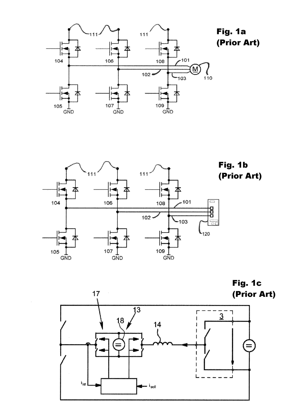
[0058]FIGS. 1a, 1b, and 1c have already been covered within the framework of the introduction to the description in the discussion of the prior art. For this reason, further explanation of FIGS. 1a, 1b, 1c can be dispensed with in the text that follows.

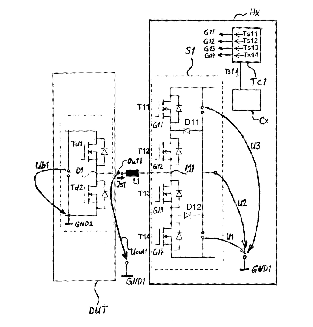
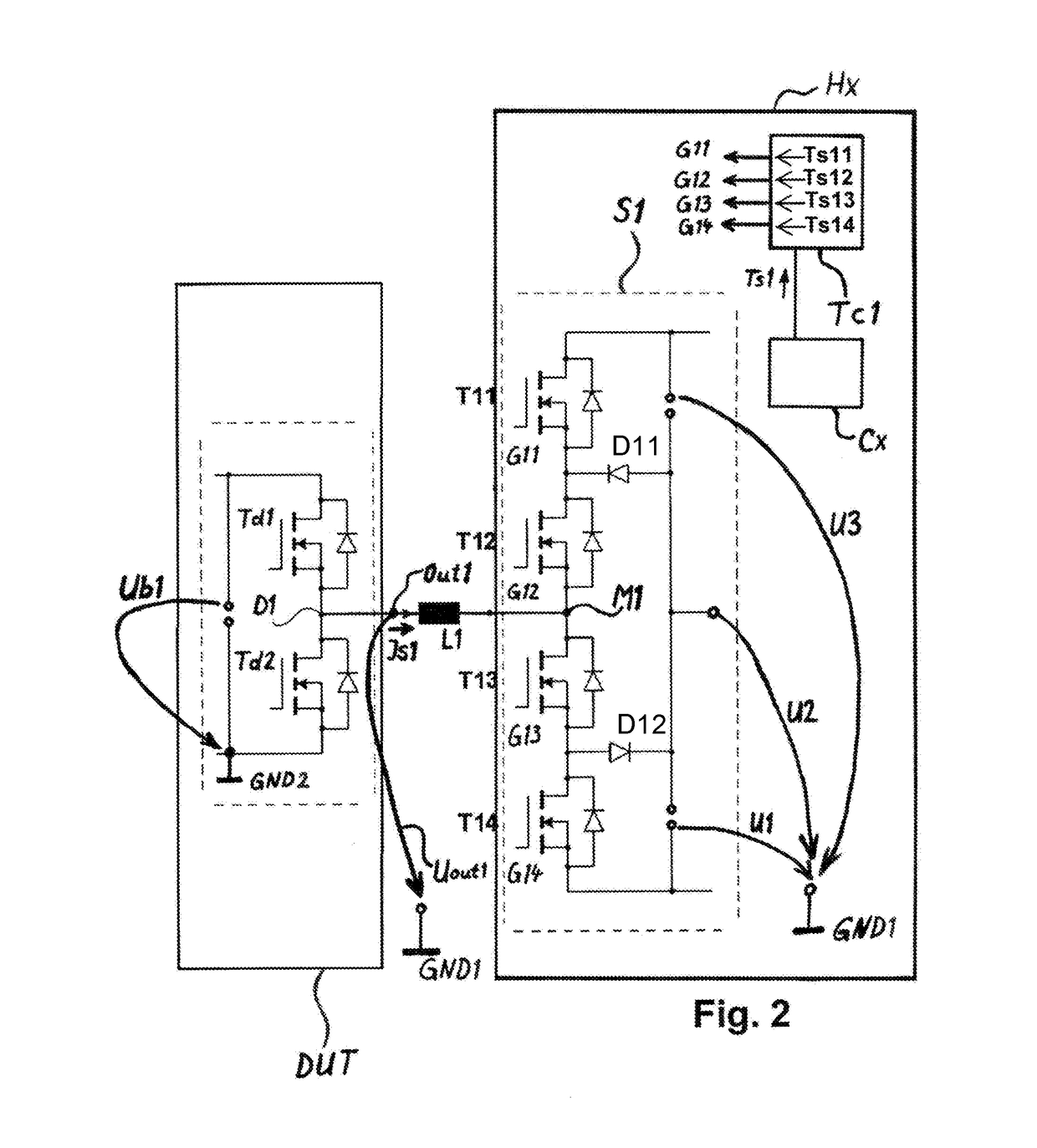
[0059]The illustration in FIG. 2 shows a view of a first embodiment of a simulation device Hx and a control device DUT electrically connected to the simulation device Hx.

[0060]The first control element S1 shown schematically in FIG. 2 includes at least four semiconductor switches, namely a first semiconductor switch T11 of the first control element S1, a second semiconductor switch T12 of the first control element S1, a third semiconductor switch T13 of the first control element S1, and a fourth semiconductor switch T14 of the first control element S1.

[0061]The last-mentioned four semiconductor switches T11, T12, T13, T14 are wired to one another and to a first supply voltage U1 or a second supply voltage U2 or a third supply voltage ...


PUM


Abstract

A simulation device for simulating a peripheral circuit arrangement that can be connected to a control device, wherein the simulation device can be electrically connected to the control device, and the simulation device has a first control element for influencing a first simulation current that can be passed from a first load terminal of the control device to a first control element output of the first control element. The first control element contains a first multistage converter that includes a first converter output, which is electrically connected to a terminal on the converter side of a first inductive component at whose terminal on the control device side the first control element output is implemented. A direction of flow of the first simulation current is reversible, and the simulation device also includes a computing unit for execution of model code.

Description

[0001]This nonprovisional application claims priority under 35 U.S.C. §119(a) to German Patent Application No. 10 2016 100 771.4, which was filed in Germany on Jan. 19, 2016, German Patent Application No. 10 2016 108 933.8, which was filed in Germany on May 13, 2016, and European Patent Application No. 16171914.1, which was filed in Europe on May 30, 2016, and which are herein incorporated by reference.BACKGROUND OF THE INVENTION[0002]Field of the Invention[0003]The invention relates to a simulation device for simulating a peripheral circuit arrangement that can be connected to a control device and a method for simulating a peripheral circuit arrangement that can be connected to a control device.[0004]Description of the Background Art[0005]A circuit for emulating—which is to say for simulating—an electrical load at a terminal of a test circuit is known from the WO 2010 010022 A1, which corresponds to U.S. Pat. No. 8,754,663, and which is incorporated herein by reference. Some elemen...

Claims


Application Information

Patent Timeline
IPC IPC(8): G06F17/50
CPCG06F17/5036G01R31/2848G05B17/02G05B2219/23446G06F30/367H03K4/06H03K4/08
Inventor MEYER, GERRIT
Owner DSPACE DIGITAL SIGNAL PROCESSING & CONTROL ENG
Why Eureka
Try Eureka