
Fuel inlet

Active Publication Date: 2017-07-20
YACHIYO IND CO LTD
View PDF1 Cites 3 Cited by
  • Summary
  • Abstract
  • Description
  • Claims
  • Application Information

AI Technical Summary

Benefits of technology

The invention reduces the amount of foam that splashes during fuel supply while also making the device lighter and less expensive.

Problems solved by technology

However, there is a risk that foamed fluid derived from fuel that has flowed back through the breather pipe flows through the fuel inlet body from the outlet of the breather pipe, and scatters outside from the fuel supply port right before such automatic stop.

Method used


Image

  • Fuel inlet
  • Fuel inlet
  • Fuel inlet

Examples


Embodiment Construction

[0033]Hereinafter, an embodiment of the present invention will be described with reference to the drawings.

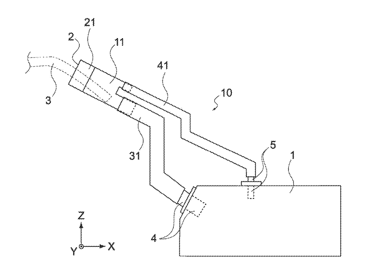
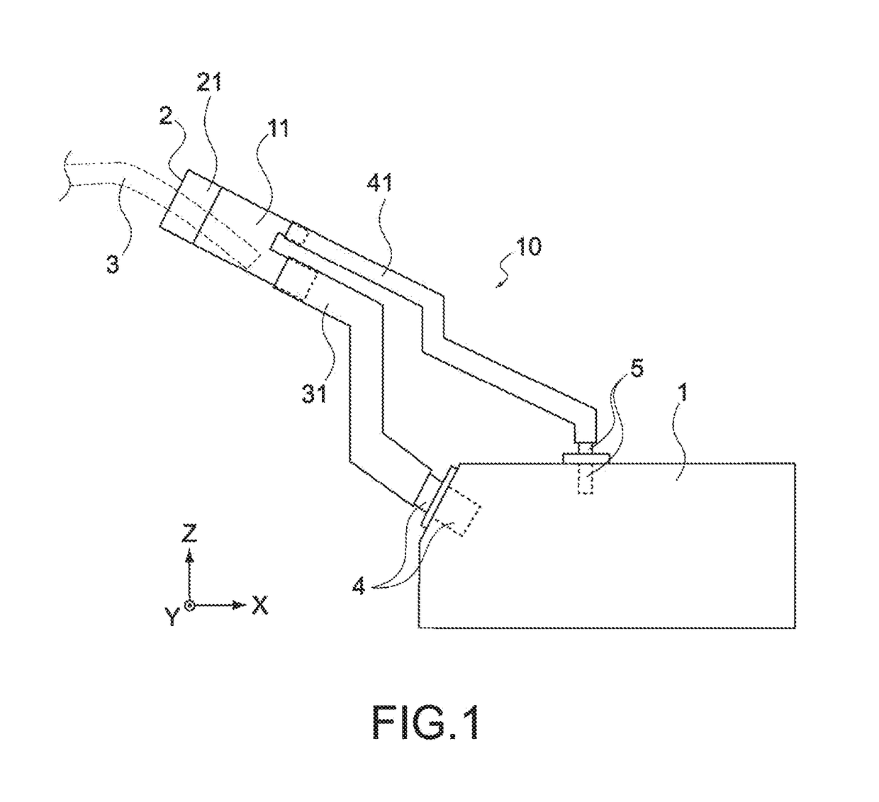
[0034]FIG. 1 is a configuration schematic diagram showing a fuel inlet according to an embodiment of the present invention, which is connected to a fuel tank.

[0035]As shown in FIG. 1, a fuel tank 1 is located at a predetermined position of an automobile (illustration thereof is omitted), and stores gasoline, light oil, or the like, which is fuel for an automobile. The fuel tank 1 is formed of an iron plate, resin, or the like. Between a fuel supply port 2 of the automobile and the fuel tank 1, a fuel inlet 10 is inserted. During fuel supply, a fuel nozzle 3 is inserted into the fuel supply port 2, and fuel discharged from the tip of the fuel nozzle 3 is supplied to the fuel tank 1 via the fuel inlet 10.

[0036]The fuel inlet 10 is a part for smoothly introducing fuel from the fuel supply port 2 into the fuel tank 1. The fuel inlet 10 has a basically pipe structure, and includes a...


PUM


Abstract

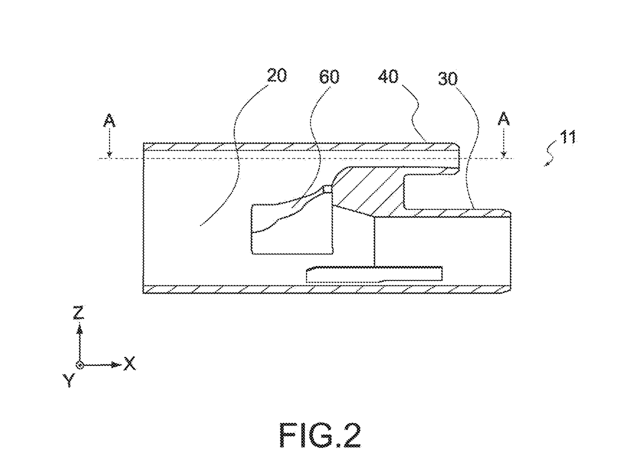
A fuel inlet 10 includes a fuel inlet body 11 that is formed of resin including a reception pipe portion 20, a filler pipe connection pipe portion 30, a breather pipe connection pipe portion 40, and a fluid introduction portion 60. The reception pipe portion 60 receives a fuel nozzle 3. The filler pipe connection pipe portion 30 is located on a lower side of the reception pipe portion 20 and is connected to a filler pipe 31. The breather pipe connection pipe portion 40 is located on an upper side of the reception pipe portion 20 and is connected to a breather pipe 41. The fluid introduction portion 20 causes foamed fluid to flow along an inner wall surface of the reception pipe portion 20 while liquefying the foamed fluid, the foamed fluid flowing from the breather pipe connection pipe portion 40 to the reception pipe portion 20. The fuel inlet body 11 that is formed of resin is formed by integrally molding the reception pipe portion 20, the filler pipe connection pipe portion 30, the breather pipe connection pipe portion 40, and the fluid introduction portion 60.

Description

TECHNICAL FIELD[0001]The present invention relates to a fuel inlet that introduces fuel into a fuel tank of a vehicle.BACKGROUND ART[0002]In a general automobile, a fuel nozzle is used to supply fuel through a fuel supply port. The fuel supply port and the fuel tank are connected to each other by a part called a fuel inlet. The fuel inlet includes a fuel inlet body, a filler pipe that introduces fuel supplied from the fuel nozzle into the fuel tank, and a breather pipe that is connected to the filler pipe on an opening side of the filler pipe and introduces air in the fuel tank into an opening of the filler pipe.[0003]The tip of the fuel nozzle is located at a predetermined position in the fuel inlet body during fuel supply. When the fuel tank is full and the liquid level of the fuel reaches a predetermined position in the fuel inlet body, a sensor provided to the tip of the fuel nozzle detects this, and the fuel supply is automatically stopped (automatic stop). However, there is a ...

Claims


Application Information

Patent Timeline
IPC IPC(8): B60K15/04B67D7/04B67D7/32B60K15/035
CPCB60K15/04B60K15/035B60K2015/0461B67D7/3209B67D7/04B60K2015/03523B60Y2410/122F02M37/00
Inventor NAKAYA, KAZUNARITABUCHI, NAOKIKOYAMA, HIRONORI
Owner YACHIYO IND CO LTD
Learn More