Systems and Methods For Stabilizing Cables Under Heavy Loading Conditions

a technology of cable stabilization and load, applied in the direction of electrical cable installation, overhead installation, adjusting/maintaining mechanical tension, etc., can solve the problems of cable load, failures are particularly prevalent, failures can occur, etc., to reduce weight and cost, improve reliability, and uniform strain levels

Inactive Publication Date: 2008-11-13
DAU PAOLO M
View PDF5 Cites 2 Cited by
  • Summary
  • Abstract
  • Description
  • Claims
  • Application Information

AI Technical Summary

Benefits of technology

[0010]An aspect of embodiments of the present invention is the replacement of rigidity, bulk, and weight, as used in prior solutions, with flexibility and adaptability by letting the sag of a cable increase between support structures in response to any load increases, and then by letting the cable regain its previous geometry, once these loads have subsided.
[0011]Exemplary embodiments of the present invention involve systems that impart to a cable the ability to extend during loading conditions and to regain its previous geometry once loads, such as ice loads, have been shed. The present invention may be utilized in any situation in which a cable, line, or cord may be subjected to variable loading conditions. Exemplary applications of the present invention include, but are not limited to, use of the present invention with anchor, angle, and dead-end structures and with suspension structures to counterbalance abnormal loads on cables and supports induced by ice and wind. In one embodiment, the use of teachings of the present invention will, in addition to improving reliability, contribute to the development of more uniform strains levels in those support structures, thereby leading to reductions in the weight and cost associated with the support structures.

Problems solved by technology

Failures in the cabling can occur as a result of stresses on the cabling.
These failures are particularly more prevalent in cabling that resides in outdoor environments.
Loading on the cable may occur due to strong winds or due to snow, ice, trees, or other items falling or resting on the cable.
During ice storms, it is not uncommon that the accumulation of ice on such lines increases the tension in those lines to the point at which the lines break or the supporting structures upholding those lines collapse, leaving many people without electricity or telephone access.
Not only do such broken lines deprive individuals of essential services, but finding and repairing those broken lines is time consuming and costly.
Unfortunately, in many cases that has not been sufficient to prevent the collapse of long sections of cables, resulting in catastrophic consequences to consumers and to suppliers.

Method used


Image

  • Systems and Methods For Stabilizing Cables Under Heavy Loading Conditions
  • Systems and Methods For Stabilizing Cables Under Heavy Loading Conditions
  • Systems and Methods For Stabilizing Cables Under Heavy Loading Conditions

Examples


first embodiment

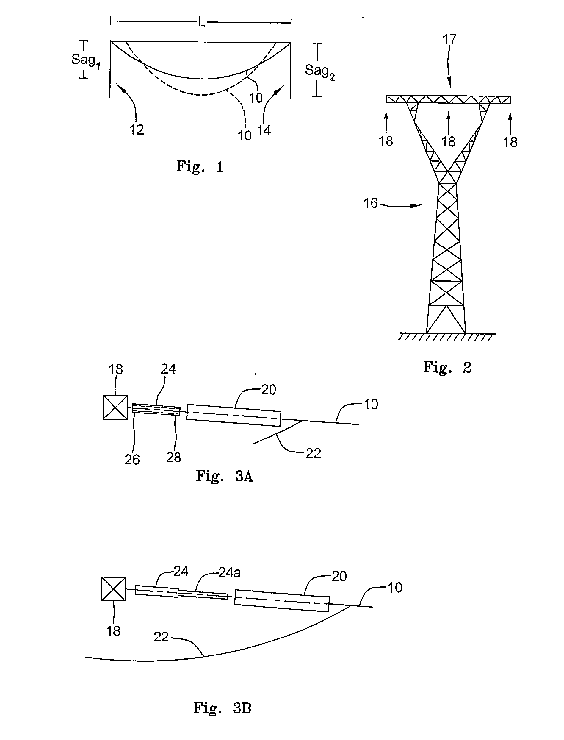
[0032]FIGS. 3A and 3B depict, respectively, an inactive state and an active state of a system embodying teachings of the present invention for stabilizing cable 10 supported from beam point connector 18.

[0033]FIG. 3A depicts the inventive system in an inactive state during normal conditions of loading of cable 10. Cable 10 connects to an insulating string 20 and is electrically connected to a similar cable on the opposite side of beam point connector 18 by a jumper 22. Disposed between insulating string 20 and beam point connector 18 is a relief brake 24 that carries the weight of cable 10 to beam point connector 18. A first end 26 of relief brake 24 is operably connected to beam point connector 18, and thus to utility tower 16, while a second end 28 of relief brake 24 is operably connected through insulating string 20 to cable 10. The body of relief brake 24 between first and second ends 26, 28 thereof is distensible in response to increased loading of cable 10.

[0034]Thus, as depic...

second embodiment

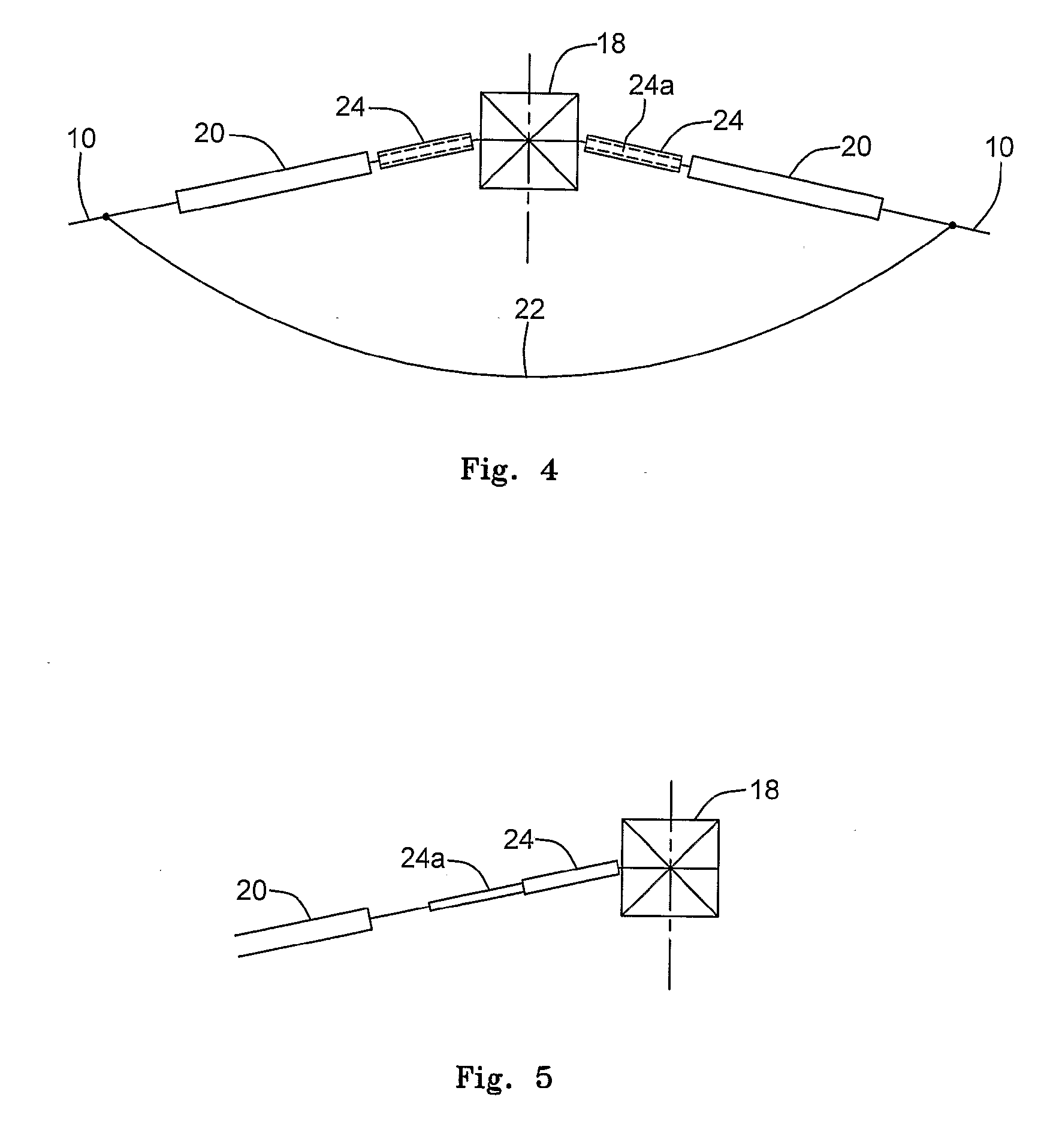
[0035]FIG. 4 depicts an inactive state of a system embodying teachings of the present invention in the system for stabilizing cable 10 upheld by an anchor or angle support structure with a support member represented in FIG. 4 by beam point connector 18. In the case illustrated in FIG. 4, on each side of beam point connector 18, a relief brake 24 is interposed between beam point connector 18 and a cable 10. Brake extension 24a is shown in dashed lines housed within the outer casing of relief brake 24.

[0036]As can be appreciated from FIG. 4, regardless of the specific implementation, one embodiment of the inventive system comprises a telescopic brake between a support structure and the cable that balances increasing cable loading, such as that encountered during ice formation the cable. The telescopic brake may be an hydraulic device or may contain one spring or a plurality of springs, or the like. As the loading on the cable increases, the telescopic brake extends in length. This inc...

third embodiment

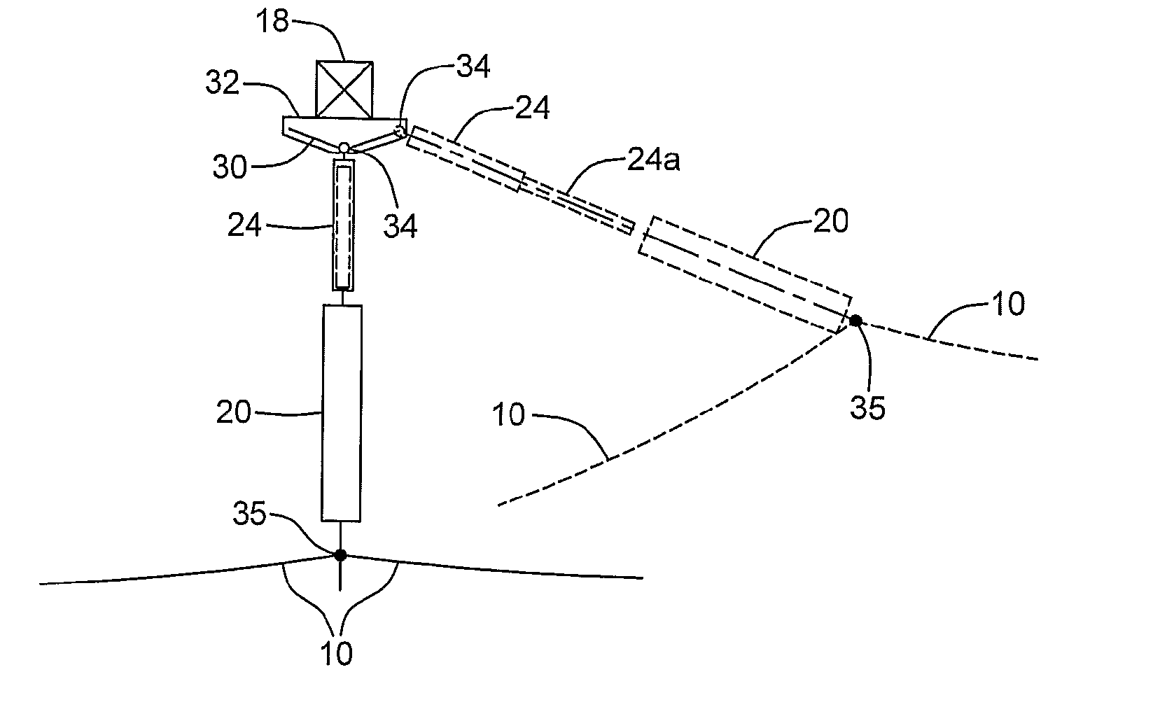
[0037]FIG. 5 depicts an active state of a system embodying teachings of the present invention for stabilizing cable 10 when being upheld by a dead-end support structure that includes beam point connector 18.


PUM


Abstract

Systems and methods are disclosed for stabilizing a wire, cable (10), line, or cord system. The present invention involves systems that allow a cable (10), such as a power line cable (10) and the insulator strings (20), the ability to extend during loading conditions and to regain their previous geometry once loads, such as ice loads, have been shed. The present invention may be utilized in a number of applications, including but not limited to, being used with anchor, angle, and dead-end structures and with suspension structures to counterbalance loads on cables (10) and supports included by ice and wind. A combination of suspension structure with anchor structure and the present invention may, on any given section of a cable (10), result in uniformity of supports and in reduction of their weight and cost, in addition to providing reliability.

Description

BACKGROUND[0001]1. Field of the Invention[0002]The present invention relates generally to the field of wire, cable, lines, or cord management, and more particularly to systems and methods for stabilizing wire, cable, line, or cord systems under heavy or variable loading conditions.[0003]2. Background of the Invention[0004]Cabling today is ubiquitous. As the number of applications and appliances that require some form of cable or wire connections increases, so does the amount of cabling. Such cabling may consists of electrical cabling to supply power to a device, a home, or an office. Cabling may also be used for data communication, such as, for example, wires for cable television, telephone lines, Internet access lines, and fiber optic cabling.[0005]As society becomes ever more reliant on the services provided by cabling, whether it is simply providing power or providing some service such as telephone access, it becomes even more important that cabling systems be protected from fail...

Claims


Application Information

Patent Timeline
IPC IPC(8): H02G7/04
CPCH02G7/02
Inventor DAU, MARIO
Owner DAU PAOLO M
Why Eureka
Try Eureka