Linear telescopic actuator

a telescopic actuator and actuator technology, applied in the manufacture of springs/dampers, shock absorbers, springs/dampers, etc., can solve problems such as blocking parts and obstacles

Active Publication Date: 2017-03-02
SAFRAN LANDING SYST CANADA INC
View PDF0 Cites 1 Cited by
  • Summary
  • Abstract
  • Description
  • Claims
  • Application Information

AI Technical Summary

Benefits of technology

The invention described in this patent enables the spring seat and cylinder to be assembled together in a simple and secure way using a few parts. This reduces the weight and cost of the assembly. The use of a resilient ring helps to distribute the forces associated with assembly over a longer length of the seat and cylinder, reducing the risk of over-stressing the blocking part. The distance between the bottom of the inner annular groove of the cylinder and the blocking part is selected to prevent interference with sliding of the seat. In this way, the blocking part always remains spaced apart from the bottom of the inner annular groove of the cylinder, ensuring proper functioning of the assembly.

Problems solved by technology

Because of the particular arrangement of the blocking part, of the inner annular groove made inside the cylinder, and of the outer annular groove made around the spring seat, the blocking part forms an obstacle to sliding and / or movement of the spring seat inserted inside the cylinder.

Method used


Image

  • Linear telescopic actuator
  • Linear telescopic actuator
  • Linear telescopic actuator

Examples


Embodiment Construction

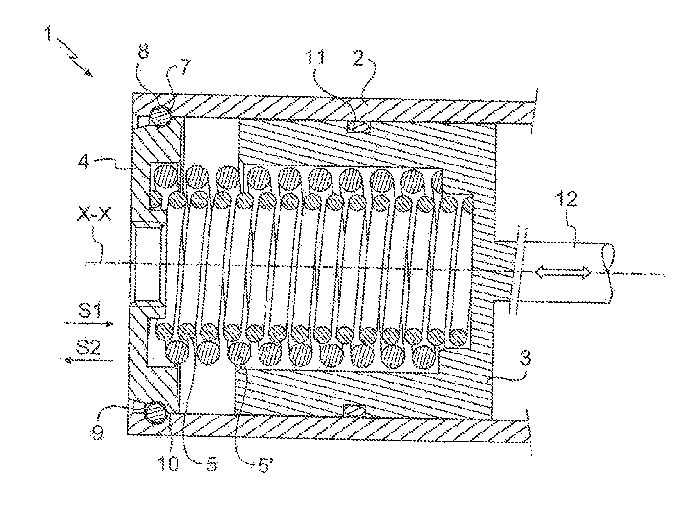
[0048]As indicated above, the invention relates to a linear telescopic actuator 1 of the telescopic linear hydraulic actuator type.

[0049]As shown in FIG. 1, the actuator 1 of the invention comprises:[0050]a hollow cylinder 2 presenting a right cylindrical inside surface of axis of symmetry X-X;[0051]a sliding part 3 extending at least partially inside the cylinder 2 in order to slide therein along the sliding axis X-X like a piston in a cylinder;[0052]a spring seat 4 that is arranged at least in part inside the cylinder 2; and[0053]at least a first compression spring 5, specifically first and second compression springs 5 and 5′ arranged inside the cylinder 2, between said sliding part 3 and the spring seat 4 in order to resiliently oppose said sliding part 3 approaching the spring seat 4.

[0054]The springs 5 and 5′ are compression springs, preferably coil springs and preferably cylindrical. These springs 5 and 5 are arranged coaxially, the first spring 5 being placed inside the secon...


PUM


Abstract

A linear telescopic actuator (1) comprising:a cylinder (2);a sliding part (3);a spring seat (4); anda first compression spring (5) capable of resiliently opposing the sliding part (3) approaching the spring seat (4).The spring seat (4) presents an outer annular groove (6) and the cylinder (2) includes an inner annular groove (7), the actuator (1) also presenting a blocking part (8), the actuator (1) being adapted to adopt selectively an assembled configuration and a disassembled configuration, the blocking part (8) in the assembled configuration being engaged inside the inner and outer annular grooves (6, 7), and the blocking part (8) in the disassembled configuration being disengaged from one of the grooves so as to allow spring seat (4) to slide in the cylinder (2).

Description

BACKGROUND OF THE INVENTION[0001]The invention relates to the field of linear telescopic actuators having a sliding part that slides inside a cylinder, together with at least one spring capable of resiliently opposing said sliding part approaching a spring seat.[0002]More precisely, the invention relates to a linear telescopic actuator comprising:[0003]a cylinder;[0004]a sliding part extending at least in part inside the cylinder in order to slide therein along a sliding axis;[0005]a spring seat that is arranged at least in part inside the cylinder; and[0006]at least a first compression spring arranged inside the cylinder between said sliding part and the spring seat in order to be capable of resiliently opposing the sliding part approaching the spring seat.[0007]In order to enable the actuator to operate correctly, the spring seat needs to be fastened relative to the cylinder in a manner that is sufficiently secure to enable it to act via the spring to exert a resilient force oppos...

Claims


Application Information

Patent Timeline
IPC IPC(8): F03G1/10
CPCF03G2730/02F03G1/10F03G1/02F15B15/1438F16F9/3242F16F2226/041F16F2226/044F15B15/1442F03G1/024
Inventor ATAMAN, GARY
Owner SAFRAN LANDING SYST CANADA INC
Why Eureka
Try Eureka