
Electromagnetic tracking surgical system and method of controlling the same

Active Publication Date: 2017-07-20
AURIS HEALTH INC
View PDF9 Cites 208 Cited by
  • Summary
  • Abstract
  • Description
  • Claims
  • Application Information

AI Technical Summary

Benefits of technology

The patent describes a system and method for tracking and controlling surgical procedures using electromagnetic technology. The system improves navigation, ergonomics, and usability, making it easier for surgeons to perform surgeries with greater precision.

Problems solved by technology

However, each of the above configurations has certain deficiencies.
For example, use of fluoroscopy may be limited in the flat configuration because the generator coils constitute radio-opaque objects / regions that can obstruct fluoroscopic imaging (for example, but not limited to, X-ray imaging).
The box configuration may interfere with a physician's access to a patient since the coils are placed externally on the side of the surgical bed or positioned above / over the patient.
In the window configuration, the positioning of coils under the surgical bed may result in mechanical and / or electromagnetic interference with other devices (for example, but not limited to, motors for actuating the bed, linear actuator drives, radio-frequency (RF) circuits, etc.) that are also disposed under the surgical bed.
Additionally, the positioning of coils under the patient may require an overall thickness of the bed to be increased, which may result in larger form factor and higher manufacturing costs.
Additional drawbacks of one or more of the above coil configurations may include limited range of use.
For example, the field generators in the above configurations typically generate a working volume of about 0.5 m×0.5 m×0.5 m, which is often insufficient to encompass a length or a width of a patient's body.
In those instances, movement of the coils around the surgical bed may be required, which may increase the mechanical complexity of the system and interfere with the physician's access to the patient.

Method used


Image

  • Electromagnetic tracking surgical system and method of controlling the same
  • Electromagnetic tracking surgical system and method of controlling the same
  • Electromagnetic tracking surgical system and method of controlling the same

Examples


Embodiment Construction

[0029]Although certain preferred embodiments and examples are disclosed below, the inventive subject matter extends beyond the specifically disclosed embodiments to other alternative embodiments and / or uses, and to modifications and equivalents thereof. Thus, the scope of the claims appended hereto is not limited by any of the particular embodiments described below. For example, in any method or process disclosed herein, the acts or operations of the method or process may be performed in any suitable sequence and are not necessarily limited to any particular disclosed sequence. Various operations may be described as multiple discrete operations in turn, in a manner that may be helpful in understanding certain embodiments; however, the order of description should not be construed to imply that these operations are order dependent. Additionally, the structures, systems, and / or devices described herein may be embodied as integrated components or as separate components.

[0030]For purpose...


PUM


Abstract

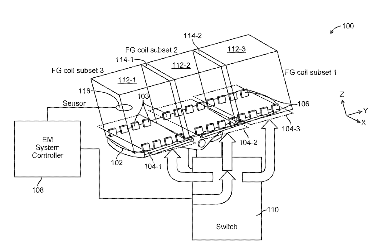
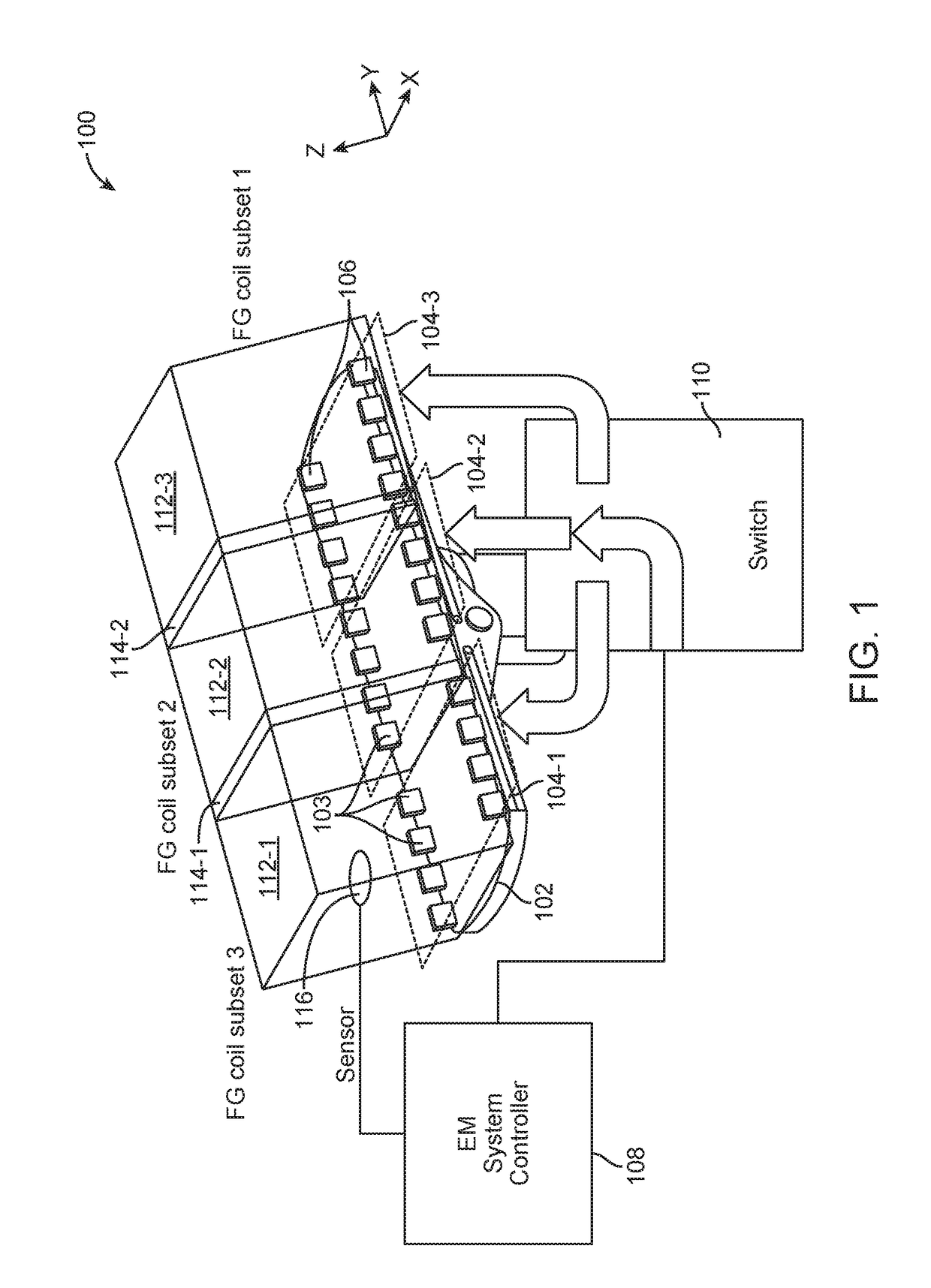
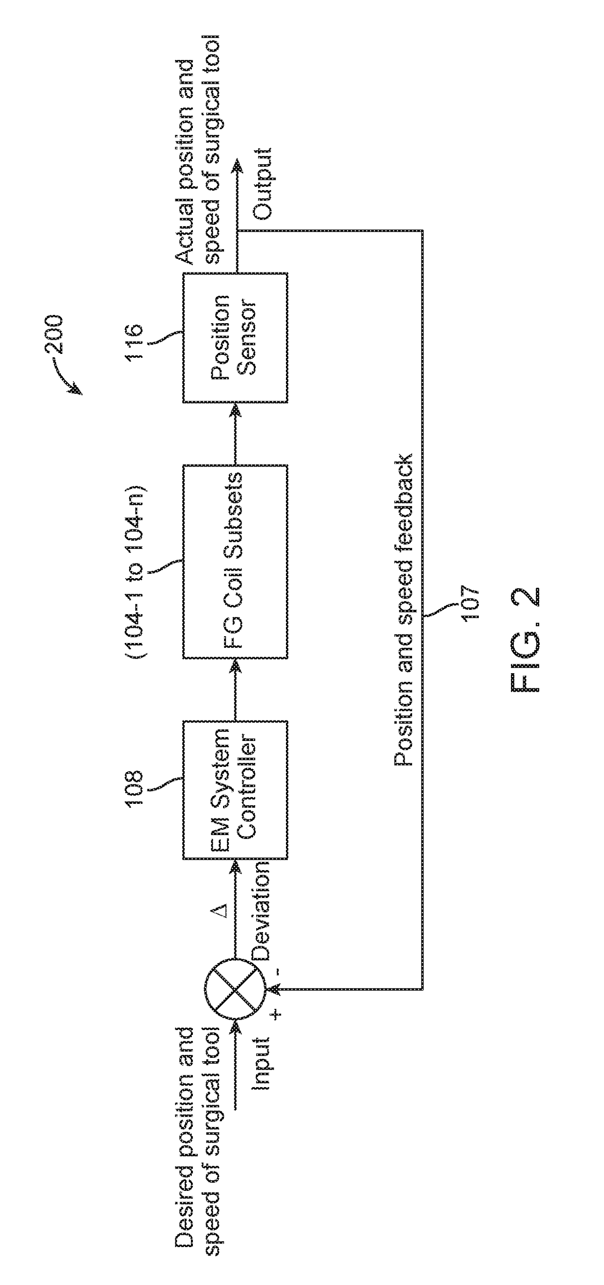
An electromagnetic (EM) system for tracking a surgical tool is provided. The system may comprise a plurality of subsets of field generator coils disposed along edge portions of a surgical bed. Each subset of field generator coils may be configured to generate a magnetic field within a control volume. The system may further comprise a position sensor disposed on a portion of the surgical tool. The position sensor may be configured to generate a sensor signal in response to the magnetic field when the position sensor is located inside the control volume. Additionally, the system may comprise an EM system controller configured to selectively activate one or more of the subsets of field generator coils based on the sensor signal.

Description

CROSS-REFERENCE TO RELATED APPLICATIONS[0001]This application claims the benefit of U.S. Provisional Patent Application Ser. No. 62 / 278,925 entitled “Electromagnetic Tracking Surgical System and Method of Controlling the Same,” filed Jan. 14, 2016, the disclosure of which is hereby incorporated by reference in its entirety.BACKGROUND[0002]1. Field of the Invention[0003]The field of the present application pertains to medical devices. More particularly, the field of the invention pertains to an electromagnetic tracking surgical system and a method of controlling the same.[0004]2. Description of the Related Art[0005]A surgical procedure may be performed on a patient using one or more surgical tools when the patient is placed on a surgical bed. The surgical tools may include endoscopes, catheters, ureteroscopes, or other similar devices. Endoscopy is a widely-used, minimally invasive technique for both imaging and delivering therapeutics to anatomical locations within the human body. T...

Claims


Application Information

Patent Timeline
IPC IPC(8): A61B34/20A61G7/05A61B34/30
CPCA61B34/20A61B2034/2051A61G7/05A61B34/30A61G13/04A61G13/06A61G13/08A61G2203/30A61B5/062
Inventor SRAMEK, CHRISTOPHERKINTZ, GREGORY J.MINTZ, DAVID S.YU, ALAN
Owner AURIS HEALTH INC
Learn More