
Lacing system

Active Publication Date: 2017-07-20
CHEN CHI HSUN
View PDF0 Cites 0 Cited by
  • Summary
  • Abstract
  • Description
  • Claims
  • Application Information

AI Technical Summary

Benefits of technology

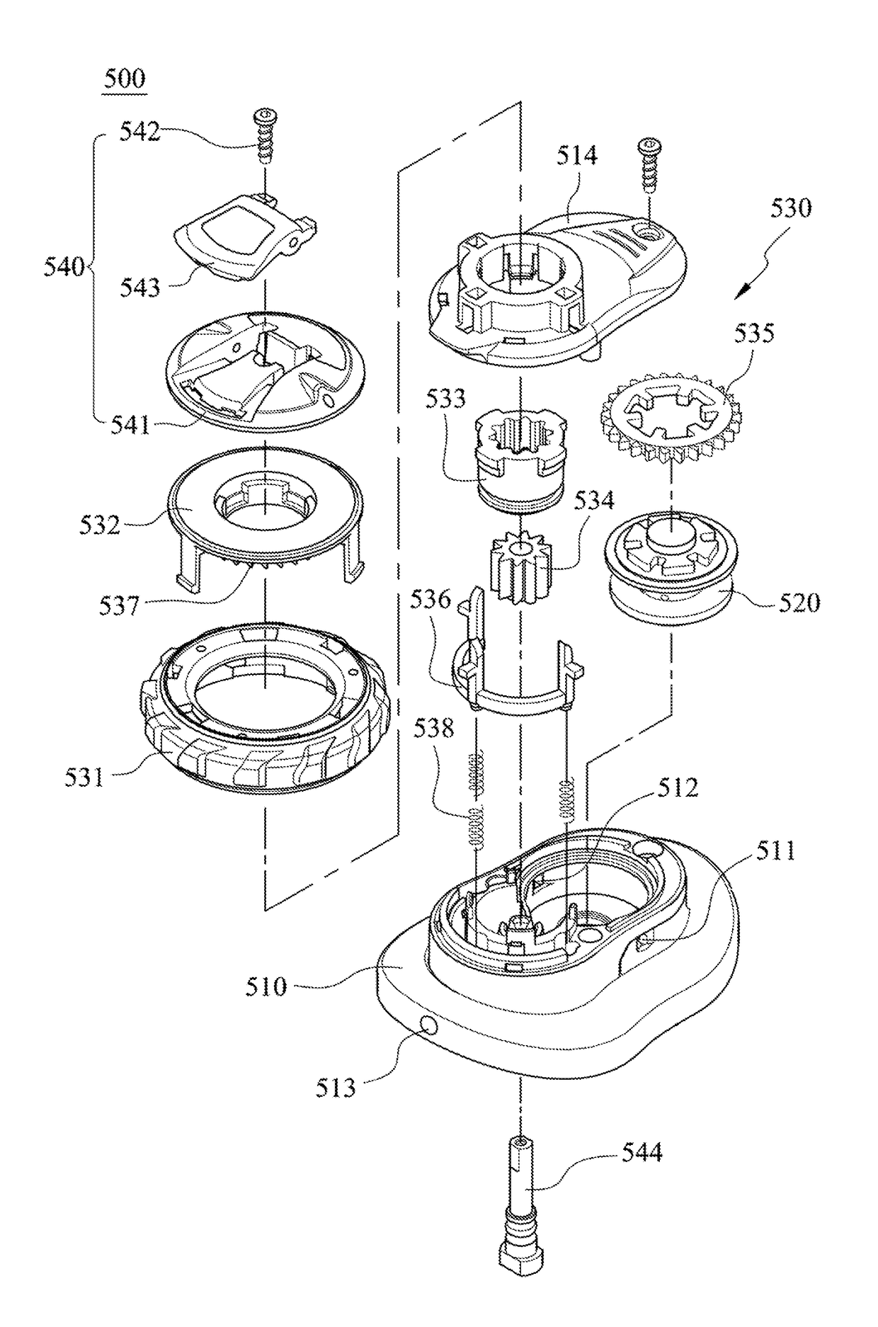
The present invention provides a lacing system to prevent l loosening of a lace and to efficiently fasten and loosen articles. The lace is balanced and the article can be quickly and securely fastened. The structure of the lacing system is simplified to reduce costs. The lace passes through a passage and is received inside the fastening mechanism, and the lace is securely fastened without being affected by external interference. The system prevents breakage of the lace and increases its life time. The lacing system is convenient, reliable, and efficient.

Problems solved by technology

However, the knots at both ends of the shoelace is easily loosed by the interference of external forces. and an accident may happen if the user is careless.
Such fastening products have lots of components, which results in high producing cost, and the fastening products are easily disabled if a single component is broken.
Besides, the user cannot maintain the fastening product himself / herself due to the complex relationships between the components.
Although the fastening products can have securing ability, they are not easily to be loosed and cannot release the article quickly.

Method used


Image

  • Lacing system
  • Lacing system
  • Lacing system

Examples


Embodiment Construction

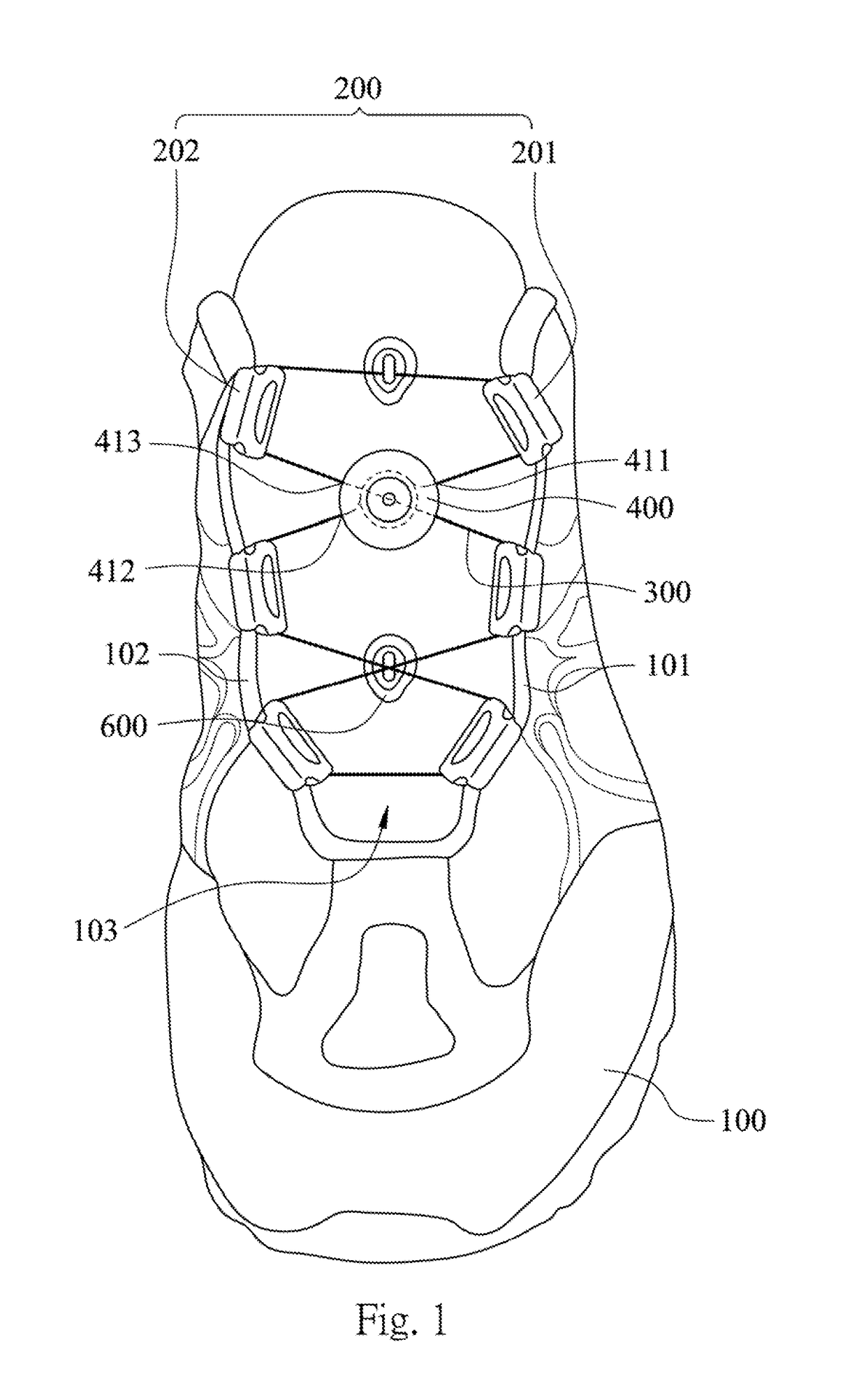
[0031]Please refer to FIG. 1. FIG. 1 shows a schematic view of a lacing system according to one embodiment of the present disclosure. In this embodiment, a shoe 100 can be deemed as the article. The lacing system includes a shoe 100, three guiding portions 200, a lace 300, a fastening mechanism 400 and two anti-friction members 600.

[0032]The shoe 100 includes a first side 101, a second side 102 and a lacing zone 103. The second side 102 corresponds to the first side 101, and the second side 102 and the first side 101 cover around the foot. The lacing zone 103 is located between the first side 101 and the second side 102.

[0033]The guiding portion 200 includes a first guide 201 and a second 202. The first guide 201 is positioned on the first side 101 and located in the lacing zone 103. The first guide 201 faces toward the second side 102. The second guide 202 is positioned on the second side 102 and located in the lacing zone 103. The second guide 202 faces toward the first side 101.

[...


PUM


Abstract

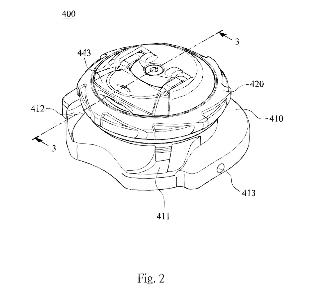
A lacing system includes an article, a guiding portion, a lace and a fastening mechanism. The lacing zone is located between the first side and the second side. The guiding portion is positioned at the article and includes a first guide and a second guide. The first guide is positioned on the first side and located in the lacing zone. The second guide is positioned on the second side and located in the lacing zone. The lace is guided by the guiding portion and extended in a zigzag pattern throughout the lacing zone. The fastening mechanism is positioned at the article to loosen or fasten the lace, which includes a housing and a reel member. The housing includes a connecting hole and a passage. The reel member is coupled to the housing to loosen or fasten the lace and is rotated along a first direction relating to the housing.

Description

CROSS-REFERENCE TO RELATED APPLICATION[0001]This application is a continuation of International application No. PCT / CN2015 / 084358 filed Jul. 7, 2015, which claims the benefits of priority of CN application No. 201420397685.3 filed on Jul. 16, 2014, the content of which are incorporated herein by reference.BACKGROUND[0002]Technical Field[0003]The present disclosure relates to a lacing system. More particularly, the present disclosure relates to a lacing system which can simplify the tying steps.[0004]Description of Related Art[0005]A lace is conventionally used with holes to tight an article, and two ends of the lace are knotted to secure or cover the article. Take a shoe as an example, a shoelace is passed through eyelets and is extended in a zig-zag pattern between two sides of the shoe. A User draws the shoelace to close the two sides of the shoe and then knots the shoelace to keep the tension of the shoelace so as to secure the shoelace on the shoe. However, the knots at both end...

Claims


Application Information

Patent Timeline
IPC IPC(8): A43C11/16A43C1/00
CPCA43C1/00A43C11/165
Inventor CHEN, CHI-HSUN
Owner CHEN CHI HSUN
Learn More