Vacuum evacuation system

a vacuum evacuation system and vacuum technology, applied in the direction of fluid pressure control, sustainable manufacturing/processing, instruments, etc., can solve the problems of increasing the installation space and the cost of the vacuum evacuation system, and the failure of the semiconductor-device manufacturing apparatus to stop its operation, so as to prevent the extraordinary increase in the suction-side pressure and reduce the installation cost

Active Publication Date: 2017-07-13
EBARA CORP
View PDF2 Cites 282 Cited by
  • Summary
  • Abstract
  • Description
  • Claims
  • Application Information

AI Technical Summary

Benefits of technology

[0035]The number of second vacuum pump is smaller than the number of first vacuum pumps, because the second vacuum pump is coupled to the plurality of first vacuum pumps through the collecting pipe. Therefore, an installation space of the entirety of the vacuum evacuation system can be small. Moreover, an installation cost can be reduced.
[0036]When the vacuum evacuation operation is switched from the vacuum pump to the backup pump, the suction-side pressure (e.g., the pressure in the process chamber coupled to the suction pipe) is lower than the pressure upper limit which indicates an extraordinary increase in the suction-side pressure. Therefore, the backup pump can continue the vacuum evacuating operation, while preventing the extraordinary increase in the suction-side pressure.

Problems solved by technology

Such a tendency entails an increase in the number of vacuum pumps used in the vacuum evacuation system, thus resulting in an increase in an installation space and a cost of the vacuum evacuation system.
As a result, the pressure in the process chamber may exceed an upper limit of a threshold value for a processable pressure, causing the semiconductor-device manufacturing apparatus to stop its operation.

Method used


Image

  • Vacuum evacuation system
  • Vacuum evacuation system
  • Vacuum evacuation system

Examples


Embodiment Construction

[0059]Embodiments of the present invention will be described below with reference to the drawings.

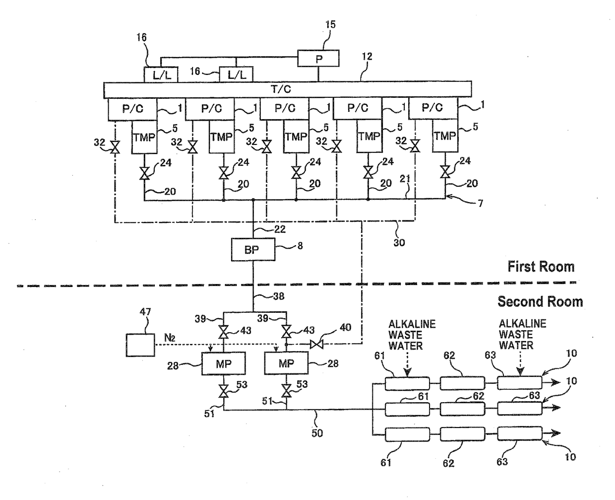
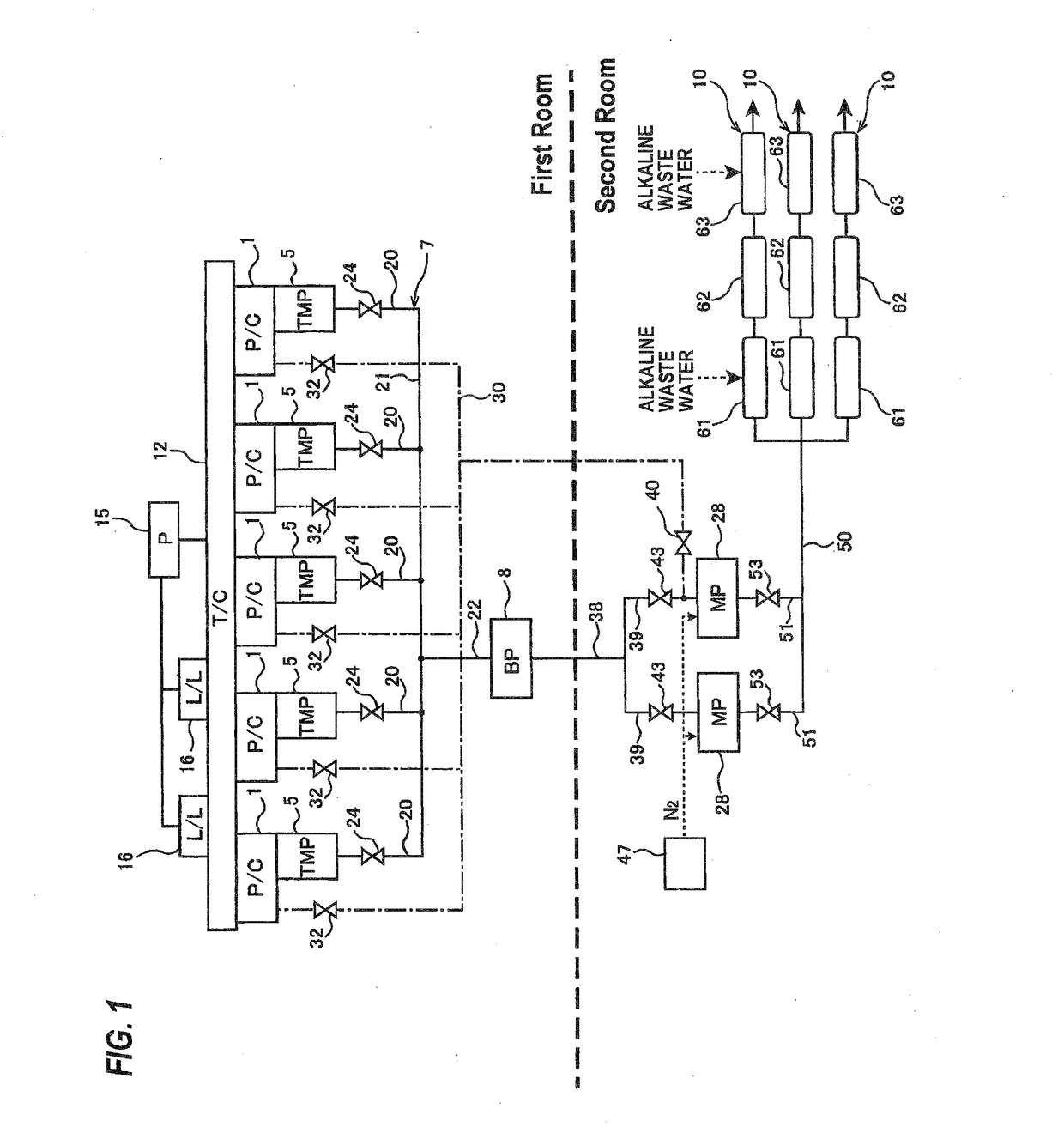
[0060]FIG. 1 is a view showing a vacuum evacuation system according to an embodiment of the present invention. This vacuum evacuation system is used to evacuate a processing gas from a plurality of process chambers used in a semiconductor-device manufacturing apparatus, such as a CVD apparatus, or an etching apparatus.

[0061]As shown in FIG. 1, the vacuum evacuation system includes a plurality of first vacuum pumps 5 which are coupled to a plurality of process chambers 1, respectively, a first collecting pipe 7 coupled to the plurality of first vacuum pumps 5, a second vacuum pump 8 coupled to the first collecting pipe 7, and gas treatment devices 10 for making a gas, which has been exhausted from the plurality of process chambers 1, harmless. In this embodiment, high-vacuum pumps, such as turbo-molecular pumps, are used as the first vacuum pumps 5.

[0062]The process chambers 1 are couple...


PUM

PropertyMeasurementUnit
back-pressureaaaaaaaaaa
atmospheric pressureaaaaaaaaaa
distanceaaaaaaaaaa

Abstract

The present invention relates to a vacuum evacuation system used to evacuate a processing gas from one or more process chambers for use in, for example, a semiconductor-device manufacturing apparatus. The vacuum evacuation system is a vacuum apparatus for evacuating a gas from a plurality of process chambers (1). The vacuum evacuation system includes a plurality of first vacuum pumps (5) coupled to the plurality of process chambers (1) respectively, a collecting pipe (7) coupled to the plurality of first vacuum pumps (5), and a second vacuum pump (8) coupled to the collecting pipe (7).

Description

TECHNICAL FIELD[0001]The present invention relates to a vacuum evacuation system used to evacuate a processing gas from one or more process chambers for use in, for example, a semiconductor-device manufacturing apparatus.BACKGROUND ART[0002]As shown in a patent document 1, a typical semiconductor-device manufacturing apparatus includes a plurality of process chambers each for processing a wafer. In these process chambers, a process, such as a chemical vapor deposition (CVD) process, an etching process, or the like, is performed on a plurality of wafers. A processing gas, such as a raw material gas, an etching gas or the like, is used for processing the wafers, and the processing gas is evacuated from the process chambers by a vacuum evacuation system.[0003]As shown in the above-mentioned patent document 1, a conventional vacuum evacuation system has a structure in which a plurality of vacuum pump units are coupled to the plurality of process chambers, respectively. These days, the n...

Claims


Application Information

Patent Timeline
Patent Type & Authority Applications(United States)
IPC IPC(8): H01L21/67C23C14/22G05D16/20C23C16/44
CPCH01L21/67017C23C16/4412C23C14/22H01L21/67276G05D16/2013F04B37/16H01L21/3065H01L21/31Y02C20/30C23C16/52F04B37/14F04B41/00H01J37/32834H01J37/32844Y02P70/50H01L21/67
Inventor SHIOKAWA, ATSUSHISUGIURA, TETSUROSEKIGUCHI, SHINICHIKYOTANI, TAKASHIKOMAI, TETSUOKIMURA, NORIOISHIKAWA, KEIICHIOSUGA, TORU
Owner EBARA CORP
Why Eureka
Try Eureka